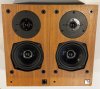
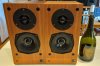
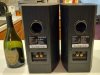
I actually had the pleasure of working on a pair of KEF Reference 101 speakers over the last few weeks. Usually, I only get sent the crossovers, but the owner of these @TAS1970 sent me the complete speakers. I was able to finally see and hear a pair of these in action, and even compare them to some of their contemporaries. But more of that later...
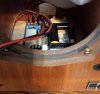
In the past, when people have asked me how to remove the crossovers, I just say "take out the center nut, and cut the sticky pads in the corners". Well, actually working on a pair, this is more difficult than it looks. First of, that center nut, you have to remove the nut, you can't remove the screw from the bottom. The reason being, it has a machine thread most of it's length, but a reverse thread that bites into the wood towards the head of the screw. The reason for this is so that the screw will not turn as you tighten the nut inside, a rather ingenious solution. This screw has a Posidriv head, as do most screws on vintage KEF speakers, so you would be advised to get a correct Posidriv bit, these are identified as PZ1, PZ2 etc.

Once the center nut is removed from the crossover, then you must break the sticky pads loose. I found the easiest way to do this was with one of those orange handled pry tools. Mine aren't a fancy brand, I can't even remember where I got them from, probably the Dollar Store. But the 90 degree one, if you drag it under the pads a few times, you should be able to lift the crossover board up and out. Don't force it, and if it feels like the board is bending, drag the pry tool under the pads some more.
Here are the crossovers removed from the speakers. On the second picture, you can see how the caps for the protection circuit have leaked, and corroded through the PCB tracks. I started removing the caps from the top board before I remembered to take pictures.
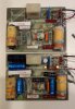

As you can see, the 400uF cap for the woofer circuit is made up of a 300uF and 100uF cap in parallel. Earlier boards have four 100uF caps, plus a different layout. Make sure you check what board you have before ordering caps, like I didn't. The picture below shows the 4 x 100uF cap board.

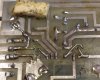
Here is a closeup of the damaged area on one of the boards. Notice how I have completly removed the corroded tracks using nothing more than a wire brush and a small flat screwdriver. You must scrape all of the corroded track away, there no point leaving any of it there, as it will just spread again and get worse. Clean the board with acetone once you are done scraping and brushing.

Fitting the new caps is always a squeeze, kind of like trying to get a quart in a pint pot. But they should go on, using hot melt glue to glue them to other components for rigidity helps, but avoid gluing to any of the resistors, as these might get hot. The big 15uF Dayton cap here has to be mounted with as little overhang as possible, otherwise the crossover won't pass back through the woofer hole and into the cabinet. Of course, if you use electrolytic caps throughout, this won't be a problem, film caps are bigger. Trial fitting the caps and seeing if they will fit will help.


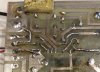
Close ups of the repaired areas show just how much work is needed to fix these PCB tracks.
Squeezing the crossovers back in through the woofer hole can be difficult with the new caps installed. I upgraded the wiring to the terminal plate and to the woofer with some thicker wire. The tweeter wires are soldered right up to the voice coil, so I didn't mess with these.
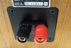
Add some 3D printed terminal plates holding some new binding posts, and the job is complete. Note the PZ1 screws for the terminal plates.
Lee.
In the past, when people have asked me how to remove the crossovers, I just say "take out the center nut, and cut the sticky pads in the corners". Well, actually working on a pair, this is more difficult than it looks. First of, that center nut, you have to remove the nut, you can't remove the screw from the bottom. The reason being, it has a machine thread most of it's length, but a reverse thread that bites into the wood towards the head of the screw. The reason for this is so that the screw will not turn as you tighten the nut inside, a rather ingenious solution. This screw has a Posidriv head, as do most screws on vintage KEF speakers, so you would be advised to get a correct Posidriv bit, these are identified as PZ1, PZ2 etc.
Once the center nut is removed from the crossover, then you must break the sticky pads loose. I found the easiest way to do this was with one of those orange handled pry tools. Mine aren't a fancy brand, I can't even remember where I got them from, probably the Dollar Store. But the 90 degree one, if you drag it under the pads a few times, you should be able to lift the crossover board up and out. Don't force it, and if it feels like the board is bending, drag the pry tool under the pads some more.
Here are the crossovers removed from the speakers. On the second picture, you can see how the caps for the protection circuit have leaked, and corroded through the PCB tracks. I started removing the caps from the top board before I remembered to take pictures.
As you can see, the 400uF cap for the woofer circuit is made up of a 300uF and 100uF cap in parallel. Earlier boards have four 100uF caps, plus a different layout. Make sure you check what board you have before ordering caps, like I didn't. The picture below shows the 4 x 100uF cap board.
Here is a closeup of the damaged area on one of the boards. Notice how I have completly removed the corroded tracks using nothing more than a wire brush and a small flat screwdriver. You must scrape all of the corroded track away, there no point leaving any of it there, as it will just spread again and get worse. Clean the board with acetone once you are done scraping and brushing.
Fitting the new caps is always a squeeze, kind of like trying to get a quart in a pint pot. But they should go on, using hot melt glue to glue them to other components for rigidity helps, but avoid gluing to any of the resistors, as these might get hot. The big 15uF Dayton cap here has to be mounted with as little overhang as possible, otherwise the crossover won't pass back through the woofer hole and into the cabinet. Of course, if you use electrolytic caps throughout, this won't be a problem, film caps are bigger. Trial fitting the caps and seeing if they will fit will help.
Close ups of the repaired areas show just how much work is needed to fix these PCB tracks.
Squeezing the crossovers back in through the woofer hole can be difficult with the new caps installed. I upgraded the wiring to the terminal plate and to the woofer with some thicker wire. The tweeter wires are soldered right up to the voice coil, so I didn't mess with these.
Add some 3D printed terminal plates holding some new binding posts, and the job is complete. Note the PZ1 screws for the terminal plates.
Lee.
Last edited: