• The move to the new server is done. There are some software and database maintenance updates in process. This has us passing the hat around to help out. We appreciate any donations. Seriously, even a dollar helps. The payment page may be found here - https://www.audiokarma.org/support.html

Kef 102.2 Refurbishing - a write-up

Gustavsson

Member
I’m currently in the process of refurbishing a pair of Kef 102.2, and while there seems to be a lot of topics covering the more popular 104.2 for example, I found little information about the 102.2. I have therefore decided to do a write-up about the process. Hopefully it can be of use or interest to some.

I should mention that I have no previous experience in re-foaming speakers, soldering crossovers etc. But fortune favors the brave, right?

This is planned as a three parts series where I cover the re-foaming of the woofer, the capacitor replacement and finally replacing the ferro fluid in the tweeter. As I am not yet done with the project I will be adding to this thread as I progress.

Part 1. Re-foaming the Woofer

Part 2. Re-capping the crossover

Part 3. Replacing ferro fluid in tweeter
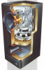
Kef 102.2.PNG
 
Last edited:

Register to hide this ad
Part 1. Re-foaming the Woofer

Kef woofer.png

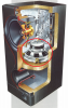
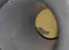
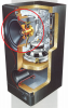
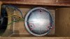
I had read prior to acquiring the speakers that they were notorious when it came to foam rot. Due to the layout of the speaker with the downward facing woofer it is difficult to assess the condition of the surround with a visual inspection. If you can’t tell by listening, you can use a flashlight and shine it down the port on the front. If you see something similar to the photo on the bottom of the speaker then you probably have a case of foam rot.

IMG_20190908_194028_1-01.jpeg

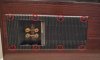
To remove the woofer we first have to remove the back plate and crossover. On the back plate there are eight screws.

IMG_20190910_194844_1-01.jpeg

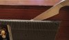
After you have removed the screws you will probably need to use a sharp knife-like object and run it around the edge in order to loosen it. The back plate is not glued on but with age I guess they tend to stick.

IMG_20190910_195311-01.jpeg

When you feel that the back plate has come loose, you will have to remove it from the bottom end first and then slide out the top (due to the size of the crossover that is attached to the back plate). Be careful and remove it slowly as there are a number of cables connected to the crossover. In my photo I have the speaker laying on its side with the bottom end on the right.

IMG_20190910_195424-01.jpeg

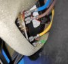
The first three cables we remove are the yellow, green and blue ones. They are detachable and should be easy to disconnect. They connect to the midrange/tweeter.

IMG_20190910_195510_1-01.jpeg

The fourth is this brown one that needs to be desoldered. There might be some silicone glue in the way, but it’s easily removed.

IMG_20190910_200202_1-01.jpeg

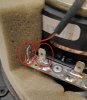
The last two wires still attached to the crossover are the purple and red. They connect to the woofer. They are soldered on to the crossover but can be detached from the driver itself. But in order to remove them we first have to empty out all the dampening material from the cabinet.

IMG_20190910_200658_1-01.jpeg

This is what the empty cabinet look like.

IMG_20190910_201051_1-01.jpeg

In order to remove the woofer we first disconnect the red and purple wires and put the crossover and back plate aside. We will come back to the crossover in the second part.

After the wires are disconnected, we unscrew the four screws. The bottom screws on either side are a bit tricky due to their placement. There isn’t much free space for tools and I recommend the use of some kind of bendable socket extension.

IMG_20190910_201150-01.jpeg

continued below..
 
With the woofer removed we can finally see the extent of the foam rot. In my case there was absolutely nothing left of the foam. The dustcap is hard plastic and should be in good condition. Except for the foam surround the driver was in good condition. (also make sure you don’t loose any of the small screws etc)

IMG_20190910_201929_1-01.jpeg

Having a look inside the cavity reveals the port and dampening material.

IMG_20190910_202014-01.jpeg

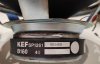
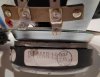
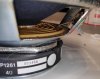
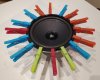
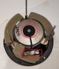
Let’s have a look at the driver. It’s a B160 SP1261 at 4ohms. Assembled on March 1, 1991 and checked by inspector #11. Third photo shows a closeup of the copper wire running from the voice coil.

IMG_20190910_205408-01.jpeg IMG_20190910_205414-01.jpeg IMG_20190910_205350-01.jpeg

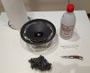
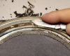
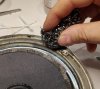
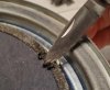
We move on to the more tedious work of removing the old foam from the cone and the steel frame. I ended up using a small pen knife (not very sharp), rubbing alcohol and some steel wool. The main idea is to just cut away and scrape off as much of the old foam as possible. Without damaging the cone. I used this video from Texasound as my main reference for both cleaning up and re-foaming.

IMG_20190910_205246_1-01.jpeg

First, we remove the old gasket. If it’s in good shape and can be easily removed without damaging it, it can be re-used. After the gasket was removed, I proceeded to scrape away most of the old glue and foam. You can soak the frame liberally with rubbing alcohol to make this process easier. Work slow so you don’t slip and damage the cone. As a final touch I used some steel wool to get rid of the last traces of the glue (the steel wool is probably a bit unnecessary though).

The cone itself is, of course, the most delicate part. Use a q-tip and wet the edge of the cone with rubbing alcohol. Make sure you support the cone on the underside with your fingers while you carefully scrape of the old glue. It’s more important that the cone isn’t damaged than it is to remove every single trace of glue. You should not overdo this part.

IMG_20190910_205444-01.jpeg IMG_20190910_210311-01.jpeg IMG_20190910_211143-01.jpeg IMG_20190910_211703_1-01.jpeg

continued below..
 
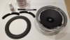
When it comes to re-foaming there are many helpful guides to watch or read. I mainly used this video from Texasound (as mentioned previously). I have also read that you can use a tone generator or a battery in order to center the cone.

The foam surround, glue and gasket were all bought from this store in Holland.

The only tool I used was a pen with a rounded end that I used to push down the edges of the foam on to the frame and cone.

I have no pictures of the procedure as I needed both hands for this.

When the foam surround and gasket had been glued in place I used some clothes pegs to keep everything in place.

IMG_20190912_200606_1-01.jpeg IMG_20190912_215914-01.jpeg


Et Voilà!
 
As a side note to the re-foam I should mention that my first driver went great. But the second one had voice coil rub prior to the re-foam. The rubbing would stop if the cone was pressed in one particular direction. I tried to center the cone by cutting away the dustcap and putting shims down the opening. I used nail polish remover to wet the spider and left it 1-2 days upside down. This did unfortunately not improve the vc rub and I decided to leave it with a repair shop. It’s been about a week and I’m still waiting to hear back from them.
 
Part 2. Re-capping the crossover

Kef crossover.png

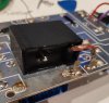
The crossover is screwed on to the back plate with six screws. The black box I’m not sure what purpose it serves, but it is held in place with silicone glue. It is not necessary to remove the box unless it sits above any of the capacitor solder joints. I used some rubbing alcohol to remove mine, because it did sit on top of one of the zip ties. I also wanted to clean up the area a little bit since the silicone glue had been applied rather sloppy.

IMG_20191002_183218.jpg

With the six screws removed we can lift up the crossover and reveal the wires that carry the signal from the speaker cables. Make sure you don’t loose the thin washers underneath the screws.

IMG_20190910_202421-01.jpeg

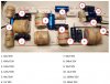
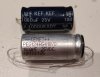
Let’s have a look at the crossover and the different capacitors. In the photo below I have listed the capacitance and voltage for each capacitor. I used Falcon acoustics as my main source for finding replacements. They did not have the same voltage for a few, but from what I have read that should not be a problem (I stepped up in voltage). There were two capacitors that I could not find with Falcon. The first one was the 240uf 25V. Instead I had to parallel two 120uf (with the help from forum members). The second capacitor was the 1000uf 25V. Instead of paralleling I decided to buy a Kemet.

I also removed and replaced the old zip ties.

I’m not advanced enough to comment on the conductors or resistance.

crossover cap list.JPG Capacitors.JPG IMG_20191002_195648.jpg IMG_20191002_194101.jpg


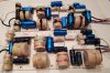
Here’s the final product. The crossover in the foreground has the new capacitors soldered on and the zip ties replaced. Removing the old solder joints was very easy when using a simple solder sucker. Using a flux pen also made soldering the leads a bit easier. In summary, this was a very basic task that anyone can handle.
Final picture shows the black box moved, the silicone cleaned up and solder joint also placed slightly different.

IMG_20191002_183915_1.jpg IMG_20191002_203756.jpg
 
Part 3. Replacing ferro fluid in tweeter

Kef tweeter.png

The project has hit a bump in the road.

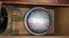
I had planned on accessing the midrange and tweeter from the inside by removing the large metal cover. It seemed to be held in place by three screws/nuts. But after removing nuts I found out that the cover was also glued directly on to the particle board. Taking in to consideration the tight space for tools etc, I don't think I can remove the cover without causing damage to the cabinet. So, if going through the metal cover is the only way of reaching the tweeter then it looks like the project ends here.

Has anyone else had any experience with removing the tweeter? Is it possible to push the whole midrange driver out the front?

IMG_20191003_213155.jpg IMG_20191003_213232.jpg
 
Last edited:
You may need to apply heat or solvent to loosen up the glue.

I have thought about using a solvent (rubbing alcohol or nail polish remover). But, I'm also worried about what type of bond the glue and particle board have formed. If the particle board would damage when trying to pry loose the metal cover. Maybe I could even out some cracks with wood filler. For heat I would have to make due with a hair dryer. I'm only missing a crowbar..
 
You found this out the same way I did (me with my 103.4's).

You dont need to remove that metal cover from the inside. As you have done - unscrew the 3 nuts and the driver then pops out the front of the cabinet - sweet as.
 
Part 3(b). Replacing ferro fluid in tweeter

After some initial confusion the removal of the midrange was actually very easy and straighforward. All you have to do is remove the three nuts on the metal cover from inside of the cabinet. Make sure you don't loose the three rubber "washers". Then just gently push the driver out through the front. The four wires that are connected to the midrange are glued in place, so don't pull too hard when removing it.

IMG_20191003_213155.jpg IMG_20191004_194000_1.jpg IMG_20191004_194320.jpg IMG_20191004_194044_1.jpg

The tweeter is attached at two places. It's wires are soldered on to the same connecting plate where we have just detached the four wires from. The tweeter itself is being kept in place in the middle of the midrange with a regular screw. After you have desoldered the wires you simply remove the screw and push the tweeter out through the middle. Be careful when doing this, you don't want to damage the midrange.

Once the tweeter is out and before separating the bottom magnet from the top, it is easier if you let the wires stay where they are and instead remove the small foam ring that holds them in place on to the base. If you start desoldering the wires you risk melting the plastic etc.

This is where my project end however. I tried to separate the magnet from the top but it was glued firmly in place. And since the tweeter is functioning I decided I didn't want to risk using too much force and maybe end up damaging it. Instead I leave a link to a post from another member that explains the process of replacing the ferro fluid.

KEF NT25 Tweeter Refurbishing

IMG_20191004_194628_1.jpg IMG_20191004_195257.jpg IMG_20191004_195801.jpg IMG_20191004_195842.jpg

I hope the thread can be useful for someone. It has been a fun project.

Cheers
 
Thought I’d resuscitate this thread as I attempted to recap the crossovers for a friend. The model is a 102.2 made in the USA under license. The cabinet is the very rare rosewood. There are 2 sets of speaker terminals to allow for bi-amping. The woofer is down firing and ported and was a PITA to remove in order to replace the rotted foam. The caps are a straightforward job as the board required only desoldering two wires. The other 8 are fastened either by clips or screw terminals. I have replaced ferrofluid in some ADS models but if the tweeter output seems OK I would suggest forgoing such an adventure since replacements are likely unavailable should the surgery go south.

While the PCB looks similar there was no mysterious black box as mentioned above On the other side I found the following caps which differ considerably:
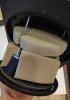
200uf
600uf
180uf
10uf
5uf
30uf
20uf
450uf
60uf

Falcon does not list a cap replacement kit on their website for the 102.2. So I’m not sure all of these caps are available. There is however some limited space which might allow for some parallel mountings should that be necessary.
 
Just bought one pair and one speaker tweet sounds much smaller than the other with not much detail. Is it a tweet problem? I checked and the woofer needs to be refoamed. Too bad that the seller claimed everything works perfectly and I did not hear test them.
 
Thank you for making this post.
I found these speakers at Goodwill for $20 USD.

Once tested I found I needed to refoam and they didn't sound all that great in the highs either, but I guess that's what happens after 30+ years.
It was my first time refoaming and first time replacing ferrofluid. The project was challenging, but I got it done in one night. Made a mistake and cut into one of the woofers, but I learned how to fix that in the process.

The end result was insane. These turned into my favorite speakers I've ever owned period. The update/restoration took them into another league of sound.

Since we set them up our family has been sitting in the living room pretty amazed.
Thank you for documenting your tutorial and experience here.
 
Since we set them up our family has been sitting in the living room pretty amazed.
Thank you for documenting your tutorial and experience here.

I'm happy to hear your refurb went well! Not having replaced the ferrofluid in my tweeters keeps me up some nights.
 
Just bought one pair and one speaker tweet sounds much smaller than the other with not much detail. Is it a tweet problem? I checked and the woofer needs to be refoamed. Too bad that the seller claimed everything works perfectly and I did not hear test them.

Did you ever get your tweeter sorted?
 
Back
Top Bottom