I thought it was time I did a write-up on my KEF 103.2 crossover upgrades. I think I'm on my third or forth one now. You can still buy the original Alcap capacitors from Falcon in the UK, but in my opinion it's not the best and/or only route to take.
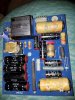
Here is a picture of the stock crossover board. The relay (blue rectangle at the top in the middle) and the components to the right are for the S-STOP protection circuit. Lots of Alcap brand non-polarized electrolytics on the board, and all iron cored inductors. Those weird looking red things are merely encapsulated circuit boards for the protection circuitry.
View attachment 657897
This shows a close-up of the underside of the board, and where a lot of problems start with these speakers. The capactitors for the protection circuit leak, and corrode the PCB tracks underneath. I have actually seen crossovers where the tracks are totally rotten through, causing the woofer to appear dead.
View attachment 657898
Not only this, but look at the path the signals have to take. The "postive signal" (well, not really, because it's AC) has to go through a long track at the top of the board to the two 300uF caps. If this isn't bad enough, look at the path the "negative" signals have to take for the tweeter, all the way around the outisde of the board, just so it can pick up on the protection relay on the way. Note also that the tweeter is wired out-of-phase, as is the case with a lot of 12dB and higher crossover designs. The woofer "negative" signal doesn't go so far, but still has to go along a thin copper track, right by an area prone to corrosion by leaking capacitors.
View attachment 657899
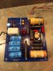
Here is the board after I recapped it, I used film caps from Erse Audio, plus a couple of their non-polarized electrolytics. There is no real reason for using the Pulse-X (black) caps instead of the MET (yellow) ones, it just depends on what they had in stock. For the two 300uF caps right at the input of the crossover, I used two electrolytics with a 10uF film cap bypassing them.
I also re-routed some of the wiring. Instead of using the long track at the top to feed the two 300uF caps, I drilled the PCB and ran my input wire right here. I also drilled the board close to where the tweeter positive connection is (remember, tweeter is out-of-phase) and attached my input wire here, rather than go right around the board. Not immediately obvious from the picture, but I also ran a black jumper wire from this negative input to the negative woofer terminal, so the signal doesn't have to go through the copper trace.
Keen eyed viewers will notice this isn't the same board as in the first picture, but that's just how things turned out, I forgot to take pictures. You may also notice I removed the protection circuit at the request of the customer. All you have to do is remove all the protection components, and jump across the relay poles with a short piece of wire.
View attachment 657900
Here is another pair I did, the picture below shows the stock board.
View attachment 657901
Once again, extensive corrosion of the PCB tracks by leaking protection circuit capacitors (circled in yellow). In this case, the owner reported that the woofer stopped working completely.
View attachment 657902
Here is the completed crossover. As I said before, there is no real reason for using Pulse-X capacitors, this time Erse had all the values I needed in stock in the MET line of caps. Careful use of hot melt glue keeps everything together. I replaced the leaking caps on the protection circuitry with Nichicon FW series, just because that was what I had in stock at the time. You can see the black jumper wire more clearly for the woofer in this picture.
View attachment 657903
The underside of the board. I made good the broken PCB tracks using the lead-out wires from the protection circuit caps. You can see the link wire for the woofer negative, I also soldered the woofer positive directly to the back of the board.
View attachment 657904
Lee.