• The move to the new server is done. There are some software and database maintenance updates in process. This has us passing the hat around to help out. We appreciate any donations. Seriously, even a dollar helps. The payment page may be found here - https://www.audiokarma.org/support.html

KEF C75 Crossover fixing: how to identify inductor values from color bands?

Chrisburrc

New Member
TL;DR
I can't figure out the value in milli Henry of the 5 inductors of the crossover. Could someone help me?


From what I understand inductors can be color coded from 3 to 5 bands. But for example the E on my crossover has only 2 bands...

I found this website with the color code input giving the mH output. I tried with the inductor B on my crossover (violet, blue, red), and it gives me the following value and tolerance: 7.6 mH, ±20%. Does it make sense to you?

Context
I'll add a bit of the story below, since there is very little information about those speakers online, hopefully it can help and save time later on for somebody else.

I got an old pair of Kef C75 one year ago. Since the beginning I realised that one was playing oddly (kind of muffed sound), so last week I finally decided to investigate. I played the whole spectrum of frequencies I realised that one speaker was not playing low frequencies anymore. I connected the low-freq driver to the second speaker, and it worked. So I deducted that the crossover of the first speaker was the problem. Since I'm about to order material and solder the components, I decided to fully replace all components of the crossover with modern elements, and see how the sound results.
 
Register to hide this ad
Good question that I'll leave to someone else to answer.
To fix you're problem, though... inductors generally don't go bad.
I would replace the caps only and visually inspect the connections to all of the components.
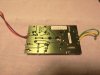
If you could upload a pic of the other side of the board, it looks like there could be bad solder connections on that PCB.

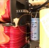
Coincidentally, I recently fixed a vintage Polk speaker that had a a similar dead speaker issue, and somehow an inductor lead got severed.
I can't imagine someone cut it, so I figured it somehow fatigued from vibration over the years.

solder.jpg

There's an insulating varnish over the copper which I scraped off with a mini file before soldering the two ends back together.
That did it, all fixed.
Lastly, an ohm-meter could easily be used to take the guesswork out of troubleshooting if you can't see anything obvious.
 
Thanks for your fast answer.

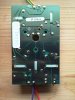
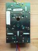
Here is the picture from below, the solder look pretty good to me. I checked the inductor leads and they look good.
 

Attachments

  • IMG_20211205_214827.jpg
    IMG_20211205_214827.jpg
    136.8 KB · Views: 41
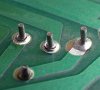
Kinda hard to see from the pic... hopefully you looked closely for a tell-tale ring around the leads.

220px-Gebrochene_loetstellen.jpg

Actually the connection to the output wire looks a bit shady.
I would order up some caps and in the meantime go over all of the connections with a soldering iron real quick right now for fun.
 
Thanks for your answers. Sorry for the bad quality pic. I just uploaded a new one. @thesteve, if you mean the HF output wire, it's because I removed them, the tweeter cables are soldered directly below the card.

@RVT1K thanks for the resource. Would you agree with the following statement, that if the inductor has only 3 bands, it means that the tolerance band has been omitted? Then I could write down the following values:
  • A: Green, blue, red: 5.6 mH
  • B: Blue, blue, red: 6.6 mH
  • C: Violet, blue, red: 7.6 mH
  • D: brown, green, red: 1.5 mH
  • E: How about this one, with only two bands?
Thanks in advance.
 

Attachments

  • IMG_20211206_132351.jpg
    IMG_20211206_132351.jpg
    111.3 KB · Views: 23
Thanks for your answers. Sorry for the bad quality pic. I just uploaded a new one. @thesteve, if you mean the HF output wire, it's because I removed them, the tweeter cables are soldered directly below the card.

@RVT1K thanks for the resource. Would you agree with the following statement, that if the inductor has only 3 bands, it means that the tolerance band has been omitted? Then I could write down the following values:
  • A: Green, blue, red: 5.6 mH
  • B: Blue, blue, red: 6.6 mH
  • C: Violet, blue, red: 7.6 mH
  • D: brown, green, red: 1.5 mH
  • E: How about this one, with only two bands?
Thanks in advance.


You're welcome.
Based on this: https://coil32.net/online-calculators/inductor-color-code-calculator.html you have the correct values, I wish I would have found that one first.
I'm afraid that I don't have any input on how to decode one with only two bands.
Have you searched for a schematic for the crossovers?
 
Hi. Sometimes I try to be too diplomatic.
THERE IS NO CHANCE ANY OF THOSE INDUCTORS ARE ANYTHING LESS THAN PERFECT.
Sorry for the all caps.

They are simply coils of copper wire. Furthermore, there have been no relevant improvements or advancements in inductor technology since they were invented.

It takes two seconds to simply touch up each solder connection and just allow the solder to flow, while slightly adding fresh solder as needed.
Cold solder connections can be very subtle and are rarely as obvious as in the photo I shared.

The circled connection looks suspect but it could be the lighting.
IMG_20211206_132351.jpg
 
The OP is not suggesting they are broken or anything else, he was replacing all components and comparing the results.

I've encountered broken inductors before in a low vibration environment so leads breaking in a speaker is not beyond the realm of possibility.
 
I think his decision to "replace all components with modern elements" was made because of his problem. Also, I already shared my recent inductor lead breaking story with him earlier (see pic above). He checked, but also my inductor was more massive and prone to vibrate. I don't think that would be the case with those small inductors laying flat. Either way... he could go to Walmart and buy a meter for $5 and check them before traveling to England to try to source replacements. : )
 
Thank you for your messages. I'm not trying to open a debate on wether or not I should replace those coils. I've read plenty of posts before and I know that people have strong opinions. I have only one question, about how to read the inductor values when there is 3 or less color bands, that's it. Thanks for your help.
 
@RVT1KWould you agree with the following statement, that if the inductor has only 3 bands, it means that the tolerance band has been omitted? Then I could write down the following values:
  • A: Green, blue, red: 5.6 mH
  • B: Blue, blue, red: 6.6 mH
  • C: Violet, blue, red: 7.6 mH
  • D: brown, green, red: 1.5 mH
  • E: How about this one, with only two bands?
If KEF built these inductors in house, as they apparently did with earlier C series models, they would only need markings for assemblers to quickly ID the parts. Tolerance codes would serve no useful purpose. KEF may well have abbreviated the standard marking scheme.

Might also explain the two-band inductor. A simple value of less than 1mH can be reduced to two bands by omitting the leading Black band. This would suggest 600μH (0.6mH) for mystery inductor "E" -- a potentially reasonable value since it's physically the smallest and also in the tweeter filter circuit.

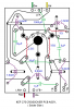
So If we plug parts values into the PCB:

xover PCB w-indctrs.png

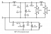
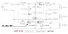
We can then trace out the schematic to see what inductor value speculation looks like in circuit.
[Edit -- updated schematic with new data from KEF (see Post 16 below)]

C75 sch.png

[Edit -- new data renders the following statement irrelevant]
Noticed after making the graphics that you've identified inductor "D" as 1.5mH (brown - green - red). Middle band looks blue in the pic on my screen. But you've got the part in real light in front of you. If it's actually green I can easily edit the graphics to reflect that.
 
Last edited:
Thank you @Stuart Pedaso! That's really cool what you did, very much to the point! Did you just draw the schematic out of the picture? I wish I had those electronic skills!

Now I have full clarity on the project and I can move forward. I'm convince that this will also help other KEF C75 owners as those loudspeaker lack resources online.
 
Now the thing that is unclear to me is that my crossover is missing the C4 condenser (I never removed it, it was like this when I purchased it). Nevertheless the tweeter is working. But according to the schema, without C4, I'd expect the tweeter to produce absolutely no sound, right?
 
Now the thing that is unclear to me is that my crossover is missing the C4 condenser (I never removed it, it was like this when I purchased it). Nevertheless the tweeter is working. But according to the schema, without C4, I'd expect the tweeter to produce absolutely no sound, right?


I agree. Is there a jumper or wire in place of the capacitor?
Does the crossover match the schematic and mechanical drawing with the exception of the capacitor or have you found other differences?
 
Nope, there is absolutely nothing. I searched on internet, it seems that there are many different layouts for this crossover. The one that I have is not exactly the same as in the specs they sent me. I did found a picture of a similar layout as mine, also missing the C4... (See attached pic). So I guess I should not bother too much with it.
 

Attachments

  • Screenshot_20211211_061531.jpg
    Screenshot_20211211_061531.jpg
    93.5 KB · Views: 29
@Stuart Pedaso The folk at KEF reverted back to me and shared the schema of the original crossover. So now we have the exact factory values.
That's fabulous product support from KEF!

And it turns out they used completely proprietary markings on their inductors. The "tables" indicate they sorted caps and inductors into tolerance variance groupings, to match up during installation. Bands on inductors might indicate which group they're from. If so, then markings could differ from one crossover assembly to another, even though the inductors have the same base values.

I've updated the schematic in post 13 to reflect now verified values. PCB shown in the pdf. is completely different from yours. It's Specification Label reads "SP2135" whereas yours is "SP2135A". Both are mentioned on the document. Though physically arranged differently they are both exactly the same circuit -- with one exception.

On PCB SP2135 the first tweeter circuit component off the + input terminal is 1Ω resistor R3, which is followed by 5μFcapacitor C4

SP2135  C4.jpg

On your SP2135A board these two components are reversed:

SP2135A C4.png

And part numbers are apparently different on your board -- both C4 and R3 are probably called something else. But the parts count, all values that can be read, and their relative connectivity are identical between the two assemblies with the noted exception.
 
Last edited:
Back
Top Bottom