• The move to the new server is done. There are some software and database maintenance updates in process. This has us passing the hat around to help out. We appreciate any donations. Seriously, even a dollar helps. The payment page may be found here - https://www.audiokarma.org/support.html

KEF C80 crossover redesign

leesonic

Captured on security camera...
Subscriber
Since I have three pairs of KEF C80s (see thread here), I thought I might try a little experiment. It seems the premise behind the design of the C80 crossover was to create a uniform 4 ohm resistive load (or as close as they could get) for the amplifier. This produced what some people have described as "the World's most complicated crossover". The amplifiers that I usually use tend to be ones that don't have problems running into low impedance loads (NAD, Proton etc). So I was wondering, would it be possible to re-design a crossover for the C80 that doesn't concentrate so much on impedance matching, instead just getting the correct range of frequencies to the right driver. Now I realise KEF probably knew best when designing this crossover, but some of us can't help tinkering with this old stuff, right?

Maybe the new design crossover could mimic something like the KEF Concerto or the Constructor series CS7? The only snag here is, the Concerto and CS7 used the B139/B110/T27 driver compliment, whereas the C80 used the B139/B160/T33 drivers. Not only but also, the drivers in the C80 were all 4 ohms, the B139 itself is the unique SP1212 version.

Think it's worth trying? I have no idea how to design a suitable crossover though. I'm cross-posting this in a couple of other forums as well.

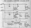
KEF C80 crossover :

index.php


KEF Concerto crossover :

KEF Concerto crossover.jpg

KEF Constructor Series CS7 crossover :
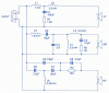
KEF CS7 crossover.gif
 
Last edited:
Register to hide this ad
Supposed to be for close to the wall, and further out into the listening room. Can't remember which one is which.
 
Do you have software to measure the driver input impedances in system?

It is a huge job to do the redesign.
 
That is a super complex crossover. Note that the tweeter has a 4th order
electrical network that probably combines with the acoustical response to be
closer to 5th or 6th order.
You have to wonder, why did they do this - probably for power handling to
minimize excursion as much as possible.

What is interesting about the impedance flattening is that it seems that they
added it close to the drivers so that the the XO upstream sees more of a
pure resistive load. This makes it difficult to remove it.

I think that C2 and the 13.3 mH compensate the bass fundamental resonance.

C7 and the 8 mH on the mid compensate the mid fundamental resonance.

It is odd that both of those networks share the resistor to ground with other parts.

Note that C13, R10 and R11 and the .3mH are directly across the input, all they
do is to flatten the midrange rise in impedance. But when it is driven by a
voltage source they do nothing to alter the input drive voltage and so do nothing
to the sound. Most solid state amps are close enough to a voltage source so
that there will be nearly no change with or without that network.
Tube amps have a higher source impedance and then the added network will
make it sound closer to the solid state since the flatter impedance does not
alter the frequency response.
 
The early B&W 801 crossover network had similar complexity but most if not all
of the impedance matching was done at the input terminals. It also had a 4th order
electrical network on the tweeter. The later revisions were _much_ simpler with
only a 2nd order network on the tweeter.

The early network was featured in an AES article on computer optimization of crossover
networks.
 
Do you have software to measure the driver input impedances in system?

It is a huge job to do the redesign.

No, I don't unfortunately, and even if I did, I would probably never get around to it.

I was thinking about how the Concerto or CS7 crossovers could be modifed for the 4 ohm drivers. They would still be set up for the B110/T27 versus the B160/T33. Maybe I should try and find a pair of these crossovers and see what happens.

Or some generic 3-way crossovers...
 
Hi leesonic. Any progress with this project? I'm looking at a rat rod pair of C80's so I wouldn't be too worried about experimenting with them. Haven't gotten them yet. Just searching around for info. What do you think of the C80's in original configuration?
Thanks,
John
 
I have also bought C80 in good condition for a small budget and I want to get the best out of them. All are critizising the small cabinet for the B139 4 Ohm.

So I would like to know If concerning the B139 there might be any option to get better LF quality out of it.

1.XO: usually you put a huge capacitor in series with the driver (CHP=closed baffle combined with high pass) to increase Q.
I don't know if the XO already has this approach in mind.

2. How about using the B139 passive radiator at the back side.

3. Are there any experience with changing the damping material?

Thanx Marcus
 
Back
Top Bottom