• The move to the new server is done. There are some software and database maintenance updates in process. This has us passing the hat around to help out. We appreciate any donations. Seriously, even a dollar helps. The payment page may be found here - https://www.audiokarma.org/support.html

Kenwood KA-5500 left channel repair

Taavip

New Member
Hello from Estonia!
Hope you are all well.

Got my hands on this really sweet '77 year Kenwood amp. Unfortunately left channel is dead.
I really like this amp, so I would like to repair and restore it.


Hopefully you can give some little guidance needed to bring this amp back to life.

Before I receive an amp I always do the following:
  • Visual inspection - ok, except some burnt area near vu meters and extra 2.3k resistors added in series for vu meter + wires(why?)
  • Initial cleaning ok
  • Check the wattage draw to avoid any shorts - ok around 20W
  • Check output voltage (dc offset) right channel ok around 5mV, left channel 2-2.5Volts
Right channel bias was adjustable and ok, rising slowly from 30mV from cold start
Left channel bias could not be adjusted really, the adjuster was able to influence from 0-5mV.
Power amp schematics:


I took out all final outputs and they measure ok, also tested q19, q21 and they measured ok. Also the resistors near power amps were ok. Does this make sense considering the dc offset of 2.5v?

Then I started to measure voltages according to schematics from right channel starting from the beginning and here are the results:
R7 14V: 14v
q1+q3 6v: -1.7v
q5 b -41.8v: -45v

q7 e 43.4v: 47v
q7 k 1.2v: 46
q7 b 42.8v: -1.2

q13 e -1.2v: -3.5
q11 e: 1.2v: -1.2

q5 b -41.8v: -45v

Please note the supply voltages are a little higher due to this amp was meant for 220v, but in reality it's 230-240v here.

So I'm seeing a problem with q1 and/or q3 and maybe q7, but not sure since one issue can affect another.

Based on these results what do you think could be the problem or problems?
I'm having a hard time ruling out either q1 or q3 and since q3 emitter voltage is affected by it's base voltage then what is affecting it's base voltage?

At the moment I try to avoid randomly taking out parts and measuring them to avoid stress for the board and I need to preorder the parts needed for this repair so I don't have a quick replacement.

By the way I have a plan to do a recap using higher quality caps and I've also cleaned the pots and switches already. Also after the power amp is repaired need to check whats the deal with the vu meters and resistors.

Appreciate your input!
 
  • Like
Reactions: mbz
Register to hide this ad
Since I'm still compiling the list of capacitors, transistors and other parts to order I investigated more of these mystical extra resistors before vu meters.
It seems someone made some extensive tuning to this amp that wasn't limited to these 2 resistors only:
  • Vu meter sensitivty switch was bridged meaning whatever the position the outcome would be the same
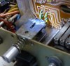
  • Vu meter sensitivity switch position resistors 120k have been replaced by 1.5k resistors, soldered on the other side of the board:
  • Tone defeat switch was bridged meaning the bass and treble buttons were always adjustable no matter the position of the switch
  • Tone defat position resistors r19, r20 removed:

  • Low filter switch bridged to stay in 1 position:
I believe this was done because the switches were at some point acting up so instead of fixing them someone went another way and just bridged/bypassed them.

I de-bridged all the switches, added missing resistors. Also from this forum found that the foam behind vu meters was causing issues, so I removed that completely and cleaned it. I put some double sided tape stripes and only revealed the upper ones to be glued to vu meters for support but also for comfortable removal when necessary, added new wires for vu-meters with the original colors:


I could test that tone defeat switch started to fulfil it's purpose again.
Also seems VU meter switch started working correctly.

However since 1 channel was not operational I could only test 1 channel and right after the left channel vu meter went to the limit and the relay protection went on.
So I will not test further until I have the left channel on the power amp fixed.

I will probably order all new transistors for power amp + spares for final output transistors for both channels just in case.
However based on my initial measures maybe someone can help me understand what is actually wrong there.
 
  • Like
Reactions: mbz
Hi. In my case the reason for not being able to set the bias was a leaky Qe10 (Qe9 on your faulty side). The Qe8 (Qe7 on your side) current generator was working ok given the reading across the resistor.

The tone defeat switch drove me crazy . Deoxit could not fix it, I did also try to open and carefully clean it but it kept malfunctioning. One channel was not going through, and I had a loud pop from the speakers when operating it. Maybe in your unit someone swapped those switches (vu-meters and tone defeat) when one went bad.

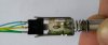
This is what I ended up doing: it works very well but unfortunately it looks ugly. I'm not exactly proud of it, but the switch was unobtanium.

IMG_20200523_190951799.jpg P1040114.JPG
 
The tone defeat switch drove me crazy . Deoxit could not fix it, I did also try to open and carefully clean it but it kept malfunctioning. One channel was not going through, and I had a loud pop from the speakers when operating it. Maybe in your unit someone swapped those switches (vu-meters and tone defeat) when one went bad.

This is what I ended up doing: it works very well but unfortunately it looks ugly. I'm not exactly proud of it, but the switch was unobtanium.

View attachment 1878134 View attachment 1878135
I've been battling the tone defeat switch too, deoxit didnt work for me either after many applications. I plan on pulling it out and cleaning it. What did you exactly do to repair yours?
 
Hi all and thanks for the replies!
For the issue with bias setting indeed Q9 was troublesome. After replacing it I could adjust bias again, however speaker was still getting 2.5Volts in the troubled channel.

I decided to fully replace all transistors including the final outputs with recommended replacements. This solved the issue and amplifier started working again.
When setting the bias, I'm now facing an interesting issue - I can not set it past a point, at the moment it's about 26mV if I try to set it higher, it will basically reset or go lower. Can it be an issue with the adjustment pot not having good contact or some other sorcery?
It's the same for the other channel.
The Right channel output is 4mV, the repaired left channel 14mV which is quite good.

I also tested the tone defeat switch which is ok when you don't touch it, but during switching it's causing some unnecessary sounds. I'll try to open and clean it, if not then actually @Tiberio your solution is not all bad if there is no better replacement available.
 
I'd be inclined to replace the bias trimmer, something like Bourns 3296Y series. Also keep in mind, the trimmer
adjusts the Vbe of Qe9. If your replacement for Qe9 had a higher Vbe than the original then the trimmer might
run out of range and not reach the wanted mV, maybe get a 2k 20 turn trimmer to allow for this extra range.
 
I think it's a good idea to replace the trimmer with multi turn one. And good to know that with alternative replacement of Qe9 the trimmer might need to be adapted.
In my case I don't think it's the issue because the bias adjustment issue is the same with the right channel where there should be all original parts.

Anyway in the next phase will probably replace all electrolytic caps, relay, new bias pots and deal with the tone defeat button.
 
I think I've managed to find a good solution to the tone defeat switch.
I desoldered it from the board and opened it up. It's not complicated, just have to be careful and do it doucement.
Then the pins and sliders are revealed.

(Ignore my dirty fingers, they've done already a lot of work)

As you can see the pins are completely covered with dirt, simply rubbing them with alcohol does nothing.

The solution is to use fine sandpaper (I think I used 600) and sand off the dirt


The result looks really good. This is followed by cleaning with alcohol and lastly cover with contact grease.
Same procedure should be done with the sliders.

I now hear almost no click when operating this button.
 
I guess you can also use some strong solvent but that would require more research and actually finding this solvent.
Do you know something that can clean that as well as the abrasive option?
 
I am really glad that the bias issue was resolved. Congrats !
@Taavip : I was doing exactly the same: open and clean, except the sandpaper part...and it did not work out for me, so I gave up and did the ugly fix. I would love to hear if it did the trick for you.

Bye
Tiberio
 
I've been battling the tone defeat switch too, deoxit didnt work for me either after many applications. I plan on pulling it out and cleaning it. What did you exactly do to repair yours?
Hi. After quite some trying I gave up and replaced the switching element with a modern one within the original mechanical part. See picture above....
 
The bias issue is not actually solved, it is set to around 26mV at the moment, but works fine. I'm not sure what the minimum value is before it would start distorting.
I'm hoping new multi turn trimmers will solve this, which I will soon order.
The sanding helped and has worked for 2 days without any unwanted clicks, but it's the long term solution that counts. As far as there is lubricant(grease) on those pins and sliders the switch should be fine.
 
I like the US market, the availability and choice of products is amazing. I've on some occasions ordered stuff from US due to non availability in EU.
Anyway toothbrush shouldn't be an issue and I should also be able to find similar deoxidizing solutions here as well.

I'll definitely give it a try next time.
 
Bit difficult to get the full range of deoxit in AU, so I've been using Silvo silver polish and toothbrush to clean such switches.
Messy and a PITA to remove all residue.
 
Back
Top Bottom