• The move to the new server is done. There are some software and database maintenance updates in process. This has us passing the hat around to help out. We appreciate any donations. Seriously, even a dollar helps. The payment page may be found here - https://www.audiokarma.org/support.html

Kenwood KA-5500 - Recap / Restore

Pugy365

New Member
Hi,

I have had this Kenwood KA-5500 for a while now, and since I have had it, it has had an issue where the left channel volume was higher than the right and after it had been running for a bit I would get scratchiness / static in both channels (Even with volume all the way down) and shortly after it would then go completely haywire and the meters fly up and down, which would then engage the protection relay repeatedly (Click, click, click, click) very fast, before I would then shut it down. This was very consistent with my testing.

So I decided to buy a restore / recap kit online as I have done this sort of thing in the past with some vintage computers, and other some other electronic equipment.
This kit also included some diodes and transistors.

After going through and doing the recap (only the power supply board, and power amp) and replaced some transistors that were included in the kit. I did not replace any diodes up to this point. I didn't want to do too much at one time as I wanted to be able to isolate issues if they occurred, as I knew what I was starting from which was a partially working unit ( at least until it warmed up a bit).

After this job I now have a unit that is worse off than it was before.
Now when I use it the output is extremely distorted as soon as any volume is applied, it sounds ok from what I can tell at minimal volume (Just barely audible, knob almost completely to the left), when any volume is applied the playback is distorted, this is on both channels.
I have double checked all the capacitors and transistors and all appear to be installed correctly (double checked NPN / PNP placement, it was right)
Also looked for cold solder joints and touched up a few places, nothing seems to change.
And to top it all off after it's been on for a bit I still get the haywire meters and protection circuit engaging (so this has to be somewhere else)

The bias adjustment does not appear to do anything, which was recommended elsewhere. (Maybe I am missing something here?)

Any help would be appreciated, I have the service manual, but I really don't see specific test points referenced, and at a loss on where I should start.
Thank you.
 
Register to hide this ad
You really need to go back over all of the work you did. Get a magnifying glass and go over all of the traces/pads and solder joints you made. Look for solder bridges, broken traces especially near any pads that may have lifted.

Are you sure about the orientation of all of the transistors? Some replacements don't have the same E B C leg layouts as the old ones.

When you say the bias adjustment does not do anything is it on both channels? Are you sure you have everything hooked up right and your meter is on the correct settings?

If you are checking & adjusting bias and nothing changes when you start to adjust the trimmer don't slam it back and forth stop to stop. If you see nothing changing stop and figure out why.

It would help us help you if you can take some pictures of the areas where you were changing parts. Front and rear of the boards. Maybe we can spot something you missed.
 
Hi @mrk229 thanks for your response, this is new territory for me so it's been a learning experience. I did carefully go over the board and all the traces, but I will go over it again. I think you could be onto something with the transistor legs being different than the original, I faced them the same orientation as the ones I replaced, and that could have very well been incorrect. I will see if I can verify this with the pinouts from the service manual. Going to check this out and will get some pictures as well.
 
Hi @mrk229 thanks for your response, this is new territory for me so it's been a learning experience. I did carefully go over the board and all the traces, but I will go over it again. I think you could be onto something with the transistor legs being different than the original, I faced them the same orientation as the ones I replaced, and that could have very well been incorrect. I will see if I can verify this with the pinouts from the service manual. Going to check this out and will get some pictures as well.
From the service manual. Unfortunately the scan cuts off some of the ID's. You can get the datasheets for the new transistors. Just google xyz datasheet.

kwtran.jpg
 
Great thanks again @mrk229 , I found that in the service manual I have and it's also cutoff but not for the ones I replaced. Whew
So you were correct on the leg layouts being different on the new transistors that were in the kit.
I did some research and looking to buy some new ones with the same legs as the original.

Here is what I was looking at purchasing for drop in replacements where the legs were the same.

OriginalNew
2SC945KSC945YTA
2SA733KSA733GTA

That being said, I still have the consistent issue from before I started repairs, where the protection circuit starts engaging after the unit has been on a while and the meters go hay wire, even with volume knob turned all the way down. This was originally suspected of being a transistor issue, but maybe it's something else? Trying to avoid replacing all the transistors if possible just not sure where to start.
 
Great thanks again @mrk229 , I found that in the service manual I have and it's also cutoff but not for the ones I replaced. Whew
So you were correct on the leg layouts being different on the new transistors that were in the kit.
I did some research and looking to buy some new ones with the same legs as the original.

Here is what I was looking at purchasing for drop in replacements where the legs were the same.

OriginalNew
2SC945KSC945YTA
2SA733KSA733GTA

That being said, I still have the consistent issue from before I started repairs, where the protection circuit starts engaging after the unit has been on a while and the meters go hay wire, even with volume knob turned all the way down. This was originally suspected of being a transistor issue, but maybe it's something else? Trying to avoid replacing all the transistors if possible just not sure where to start.
You don't need to get new transistors with the same lead layout. We deal with this all the time. A simple little twist gets you what you need most of the time.

What do you have as replacements now?

When it acts up do both meters seem to behave the same (is the noise in both channels)

As for dropping into protection you need to determine why it is happening. My first guess is that the offset voltage is drifting over time and triggering the protection circuit.

That is easy enough to watch for. The 5500 does not have an offset adjustment. If it is the offset you will be more than likely replacing the power amp differential pairs.
IME that is the most likely cause.

Ideally the offset voltage will be in the low 10's of mV DC + or -.

You can monitor the offset voltages of the amp channels in several spots. As a baseline check you connect the plus lead of your meter to a speaker output terminal and the ground lead to the chassis. Turn the amp on and with no audio see what the voltage is. It should be fairly stable but it will wobble around.

It may be a plus or minus voltage or it may go back and forth if it is near zero. Watch it for a while and see what it does. If it keeps going up in value (polarity does not matter for this) that channel has a problem and if you keep watching it go up at some point the protection will trip. Once it trips the speaker terminals will no longer be connected so the meter will drop to zero.

Do this for both channels, if you have two meters do both at once.

Let us know what you observe.
 
Ok I had already ordered the transistors as they were pretty inexpensive, and I may not have left enough length on the original replacements (PN2222A & 2N2907A) to do the twist method anyway easily, I will keep this in mind in the future though, great tip. Thanks for all the help, learning a lot! @mrk229

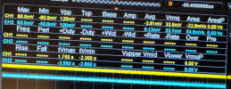
This troubleshooting gave me a good reason to open up and learn how to use my new Rigol oscilloscope, as it has multiple channels it worked perfect for this. It was not really a gradual increase, it remains relatively stable at the below measurements, until all of a sudden the (Left Channel, CH1 on scope) starts to act up after it's been on a bit (about 30 minutes).

It stayed around these levels for pretty much the entire time until protection was tripped.

Screenshot 2025-04-01 at 8.41.51 PM.png

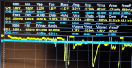
After about 30 minutes, this happens, and the protection circuit engages, and meters go hay-wire (Right meter not as much but it seems to move as well)

Screenshot 2025-04-01 at 8.41.38 PM.png

Notice the left meters goes to the right (increases) and the right meter seems to go left (decreases).
Screenshot 2025-04-01 at 8.45.06 PM.png
 
A scope, awesome. They are a very useful tool. It is showing the problem to be in the left channel. The right (magenta) looks to be very stable over time.

Have you replaced any transistors in the power amplifier part of the circuit? Likely cause is the differential pair.
 
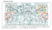
Yes excited to start getting some use out of it, it's a pretty neat tool. I only replaced the transistors in the orange boxes, and if I understand correctly I need to replace the ones in the red boxes at least for the left channel. I found the KSA992FTA as a replacement since I did not have any of these from the kit, they were originally 2SA763WL.
Screenshot 2025-04-02 at 9.26.25 AM.png
 
Yes excited to start getting some use out of it, it's a pretty neat tool. I only replaced the transistors in the orange boxes, and if I understand correctly I need to replace the ones in the red boxes at least for the left channel. I found the KSA992FTA as a replacement since I did not have any of these from the kit, they were originally 2SA763WL.
View attachment 3470772
The orange box transistors are part of the overdrive protection, not really part of the audio path. They could cause issues though.

Yes the KSA992FTA or the now current KSA992FATA would be the replacement for Qe1 through Qe4. Since this amp does not have an offset adjustment you need to pair match them the best you can. Do you have any kind of transistor tester that shows HFE?
 
Ok the ones in the orange boxes are all definitely not installed correctly based on the leg pinout you mentioned earlier, surprised the over drive protection is working at all. Do you think that would have caused the distortion issues if it's not in the audio path? Ok great, I ordered a dozen of the KSA992FTA as they had those in stock at mouser. I do not have a transistor tester, is there one you would recommend?

Drok Transistor Tester I found this one on Amazon.
 
Ok the ones in the orange boxes are all definitely not installed correctly based on the leg pinout you mentioned earlier, surprised the over drive protection is working at all. Do you think that would have caused the distortion issues if it's not in the audio path? Ok great, I ordered a dozen of the KSA992FTA as they had those in stock at mouser. I do not have a transistor tester, is there one you would recommend?

Drok Transistor Tester I found this one on Amazon.
It would depend on how serious you are about the hobby. You have a scope so that shows a level of commitment.

A lot of these low $ ones out there and I have a few. These are multi-component which makes them handy for quick testing or even just identifying transistor pinouts. No endorsement on either one just examples.

The Drok is a variation of the two I listed. They all have pretty much the same features.

A step up would be one of these. https://a.co/d/0v7eYL5 These are very nice, easy to use devices.


The over drive circuit could be causing the distortion. Sort that problem out first and then run the offset test again with the scope. You mentioned the amp had issues before you started so my $ is still on the diff pair.

Do you have any freeze spray? Even canned air will work if held upside down. Run the offset test with the scope hooked up again and when you start to see the noise & voltgae spikes spritz the diff amp transistors on that channel and see if it settles down.

Where are you getting your parts from?
 
I enjoy working on vintage electronics in general so it would most likely get used again. The scope was my first major purchase, I had bought some older scopes but they never seemed to work accurately so bit the bullet and bought a new one that had some decent reviews. I am slowly growing my knowledge from simple capacitor replacement to more complicated repairs so I don't mind investing a bit more, so going to purchase that better transistor tester.

I did not have distortion until I replaced the transistors mentioned above (Over drive circuit), only major issue before was the over drive protection engaging after a bit of use which has been consistent. So I will get those sorted out and then move on to the diff pair, which I think you are correct at those being the problem. I think I have some canned air around here somewhere, I will look.

I purchased my parts from mouser.com since they had them all in stock, sometimes I use Digikey as well.
 
It can be a rewarding and fun hobby, some folks make it more than a hobby and can make a little pocket money repairing & rehabbing vintage gear.

Just like a mechanic good tools make a difference, but of course you need to know what to do with them.

The DCA55 will serve you well. When you get around to matching transistors don't handle them with your fingers. the heat from touching them will make the HFE change.

If they are on cardboard tape then just handle the cardboard. If you have individual transistors use tweezers to handle them. The cardboard tape ones are great you can test a bunch and write the HFE value under each transistor.
 
Last edited:
Very rewarding for sure. I didn't get a chance to use the freeze spray before the parts came in. So I finished up all the repairs we discussed and I now have a fully working unit! I was able to test the HFE like discussed and find matching pairs for the differential pair transistors. I also replaced all the over drive protection circuit transistors and triple checked the pinout. The ones I ordered still didnt have the same legs, so I had to use the twist method and some wire insulation to prevent any shorts.

After all the repairs I now have clean audio with no strange issues with the left channel, I ran it for a couple hours over the weekend and its sounds great! Here is a picture of the setup so far I thought I would share. I have the Kenwood paired with a set of ADS L620s. Very happy with the repair, and thanks again for all the help @mrk229 Screenshot 2025-04-07 at 3.01.14 PM.png
 
Very rewarding for sure. I didn't get a chance to use the freeze spray before the parts came in. So I finished up all the repairs we discussed and I now have a fully working unit! I was able to test the HFE like discussed and find matching pairs for the differential pair transistors. I also replaced all the over drive protection circuit transistors and triple checked the pinout. The ones I ordered still didnt have the same legs, so I had to use the twist method and some wire insulation to prevent any shorts.

After all the repairs I now have clean audio with no strange issues with the left channel, I ran it for a couple hours over the weekend and its sounds great! Here is a picture of the setup so far I thought I would share. I have the Kenwood paired with a set of ADS L620s. Very happy with the repair, and thanks again for all the help @mrk229 View attachment 3475606
You are welcome.

Nice Stack. The KW's look great in the wooden cases.
 
Back
Top Bottom