


Here's an interesting one. I have a Kenwood KA-6004 amplifier, I brought this up from the basement a couple of months ago to have a look at it. The outputs look like they had been installed with heatsink compound from a caulk gun, and the screws all seemed kind of loose. I took them all out, cleaned them, and tested them, they all tested fine. I found the correct sized screws in my spares bin, and reinstalled them with some sil-pads which were all I had at the time. I checked for shorts at the outputs (shouldn't be any) and the drivers, everything seemed fine. Plugging the amp in (via a DBT at first), the protection relay didn't click off, but the offsets at the outputs were -43mV and -20mV. These can be measured at pins 16 and 20 on the power board, where the emitter resistors live. I think there is something else going on with the protection circuit. And there it has sat for two months.
Today, I sat down and had a look at it. At first, I thought the relay driver transistor Qe17 had gone bad, like they do in other Kenwood amps. I replaced this, along with Qe17, Ce16 and De11. Still nothing. So it was time to look closer at the schematic, and see what was going on instead of making educated guesses.
This amp is a real pain to work on, because there is no easy way to get to the back of the board to probe for voltages. I did it the only way I know how, by soldering lengths of insulated solid core wire onto the test points. The one saving grace is, the driver/power amp board is socketed, so it's easy to lift out to attach said test wires.
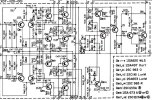
There are three places on the power amp where the schematic shows 0V should be measured. This is at the junction of the emitter resistors for the driver transistors Re23/Re25 and Re24/26. These are laughably shown on the schematic as 330K, but they are actually 330 ohm. There is also the input to the protection circuit at Ce15 and the junction of diodes De7/De8. I have labelled these as test points 1,2, and 3, shown on the schematic in red.
Measuring these three points, TP1 and TP2 measured 0V as indicated, but TP3 was around 6V. Lifting a leg of Re27 and Re28, TP1 and TP2 stayed at 0V, but TP3 went up to 10V.
Now, there are three more points we need to look at. The emitters of Qe13, Qe14 and Qe15 should all be 37V with everything being well. These I have labelled as test points 4, 5 and 6.
Reinstalling Re27 and Re28, and measuring these three points TP4 and TP5 showed 38.6V but TP6 showed only 8.7V. Lifting a leg of Re41, the amp powered on and the relay clicked off. I replaced Qe15 (and Ce15 for giggles), reinstalled Re41, and the amp powered up and the relay clicked.
I took the liberty of cleaning the relay contacts, the speaker switch contacts, and also the normal/separate switch that splits the pre and power amps. I had it playing for about two hours today.
Hope this helps,
Lee.
Today, I sat down and had a look at it. At first, I thought the relay driver transistor Qe17 had gone bad, like they do in other Kenwood amps. I replaced this, along with Qe17, Ce16 and De11. Still nothing. So it was time to look closer at the schematic, and see what was going on instead of making educated guesses.
This amp is a real pain to work on, because there is no easy way to get to the back of the board to probe for voltages. I did it the only way I know how, by soldering lengths of insulated solid core wire onto the test points. The one saving grace is, the driver/power amp board is socketed, so it's easy to lift out to attach said test wires.
There are three places on the power amp where the schematic shows 0V should be measured. This is at the junction of the emitter resistors for the driver transistors Re23/Re25 and Re24/26. These are laughably shown on the schematic as 330K, but they are actually 330 ohm. There is also the input to the protection circuit at Ce15 and the junction of diodes De7/De8. I have labelled these as test points 1,2, and 3, shown on the schematic in red.
Measuring these three points, TP1 and TP2 measured 0V as indicated, but TP3 was around 6V. Lifting a leg of Re27 and Re28, TP1 and TP2 stayed at 0V, but TP3 went up to 10V.
Now, there are three more points we need to look at. The emitters of Qe13, Qe14 and Qe15 should all be 37V with everything being well. These I have labelled as test points 4, 5 and 6.
Reinstalling Re27 and Re28, and measuring these three points TP4 and TP5 showed 38.6V but TP6 showed only 8.7V. Lifting a leg of Re41, the amp powered on and the relay clicked off. I replaced Qe15 (and Ce15 for giggles), reinstalled Re41, and the amp powered up and the relay clicked.
I took the liberty of cleaning the relay contacts, the speaker switch contacts, and also the normal/separate switch that splits the pre and power amps. I had it playing for about two hours today.
Hope this helps,
Lee.

