• The move to the new server is done. There are some software and database maintenance updates in process. This has us passing the hat around to help out. We appreciate any donations. Seriously, even a dollar helps. The payment page may be found here - https://www.audiokarma.org/support.html

Kenwood KA-7002 Idle current Adjust Proceedure

Siraudio85

New Member
Hello everyone, I have been struggling with my KA-7002's Idle current adjustment. Unfortunately the service manual isn't so clear.
So far I have:

Connected 2 dummy loads of 80ohms each to each channel on speaker terminals.
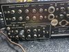
Connected a 1 Khz signal through aux port. (Manual says main but if I do it wont play the signal through speakers?). Also I'm not sure how much volume I should be giving it.
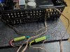
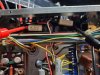
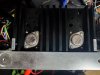
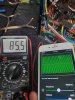
I'm not sure about how/where to connect the leads to check for the 50mA it calls for.

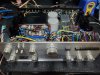
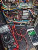
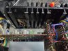
Any help much appreciated ! upload_2023-4-6_22-33-39.png20230406_192609.jpg 20230406_215709.jpg 20230406_215716.jpg 20230406_215447.jpg 20230406_215453.jpg 20230406_215557.jpg
 

Attachments

  • 20230406_192622.jpg
    20230406_192622.jpg
    206.4 KB · Views: 20
  • 20230406_215611.jpg
    20230406_215611.jpg
    113.7 KB · Views: 17
  • 20230406_215724.jpg
    20230406_215724.jpg
    162.3 KB · Views: 18
Register to hide this ad
Probably best to move thread to Kenwood sub forum, guru's there will have first hand knowledge.

Connected 2 dummy loads of 80ohms each to each channel on speaker terminals.
typo right, should be 8ohm load

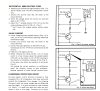
The diff amp stage is about testing the DC offset. Measure as per fig 1 ie, common point between emitter resistors and GND/chassis. If you are unsure then measure between red and black speaker connectors (need to select spkr A or main), Ideally 0mV, under 20mV is good and under 50mV ok...

The procedure/graphics for idle current don't appear ok.
The signal generator and oscilloscope are for checking the waveform for any crossover distortion and clipping. If you don't have an oscilloscope then go for the simplified procedure and connect your DMM across the emitter resistors, appears that you've done this correctly in the pix, double check that the probe connects to the transistor emitter. Bias current (mA) = bias voltage(mV)/0.94, close enough if you set voltage to 50mV (between the two emitters/resistors)

Graphic shows to measure between collectors but would have to subtract Vce...
 
Back
Top Bottom