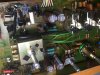
---Update---
I finally did it. It took time, but now I get the correct readings. It turned out that the STV-4H diodes are fine and not the issue in this amp. I started going through the thread mentioned above, following
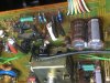
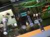
@dr*audio suggestions, and got a impression that diodes need replacing. But I was wrong. I made the diodes as suggested in one of the threads here on AK, and it turned out great (will post pictures and readings below). Somehow the DIY diodes were giving even higher mv readings. Placed back the original diodes and continued with the testing. What I did wrong, was that I tested the pots some what incorrect. Taking them out and doing resistance check, it showed 120 ohms, while it should be 100 ohms (this is what manual says). So they were either dirty or bad. Since I had new 33 ohm resistors that were needed in R5 and R6 place, I swapped them too. I ended up with a correct mv reading on the right channel, but still had bias creeping up on the left. I then started swapping some of the resistors near the bias pot, and found one of the resistors being 20 ohms, instead of 27 ohms, on the left channel. Rechecking bias, still nothing. Got maybe 1-2 mv down, but it was still 10mv above the reading I needed. I was losing hope at that moment, since most parts around the bias pot were new. Then I thought that it would be good to check D7 and D8, the 1S2076 diodes. And here, this is where the problem was. The good diode showed 0.6v and a bad diode was showing 0.15v. I swapped them with a 1n4148 diodes, and boom! It is now more or less rock stable at 26mv on both sides. I get some small changes, like "25.8" or "26.2", from time to time, but it is almost all the time showing 26.0mv. This is after running amp for 10 minutes or more. DC-offset is almost at 0.0mv, but likes to jump up a bit here and there, so I would say +-0-1mv is where it stays. New pots are needed, but since I don't have them in stock, I need to order them. All in all, I'm happy it's finally done. Took me some, but I learned something new.
STV-4H diode replacement part DIY guide/how I did it.
I followed this thread
https://www.audiokarma.org/forums/index.php?threads/replacing-the-stv-3h-and-4h-diodes.279530/ and found out that 4 of the UF1004 diodes in series, is more or less ideal for the substitution. Since not that many showed step by step guide on how to make one, I made some photos under making, so that someone can use it as some sort of a guide.
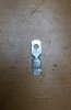
I started by finding some "speaker terminal" type connectors.

Then I drilled a bigger hole, so that the mounting screw goes through it without problems. Removed the red plastic thing and hammered it flat.
Glued diodes together closely, just to make soldering easier (this part can be skipped if you want to save time).
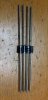
Soldered them in series as this.


Attached some long wires, so that I don't need to worry about them being short or something. I used some thing wires extracted from CAT5E cable.
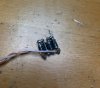
And this is how I planned having it (an illustration how it looks before glue comes on top).
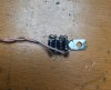
After gluing it together, it looks something like this. I used "steel epoxy" from Biltema (scandinavian shop), which is an equivalent of a JB Cold Weld I believe. It has better heat resistance than the normal epoxy glue.
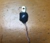

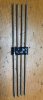
Works fine, but is a bit bigger that the original STV-4H diodes. Not by much, though. In the kenwood amp, they fit just as nice as the originals.
Results: it shows stable 1.9-1.915v. Original STV-4H diodes show 1.95v (at least the ones I have). Not sure why, but I was seeing higher BIAS mv readings with these than the originals. So I will just be keeping these as "spare parts". Maybe 4 of UF1004, in Kenwood is not the right substitution. Or my way of making diode is bad. Anyway, you don't need to follow the way I did it. Just posting it, so some of us, who are a bit more "green" in electronics, can get a better idea on how to make it (get some ideas too, maybe?).