• The move to the new server is done. There are some software and database maintenance updates in process. This has us passing the hat around to help out. We appreciate any donations. Seriously, even a dollar helps. The payment page may be found here - https://www.audiokarma.org/support.html

Kenwood KA-7100 comes out of protection only when warmed up (a lot).

Owl

New Member
Got a KA-7100 that I had to re-do the on/off switch on, and replace the LED. That work came out fine.

Now... the system comes out of protection ONLY when it REALLY gets warmed up (like over 5 or 10 minutes on).

Once it gets warmed up like that, I can power it off, then power it up, and it only takes like 5 seconds to hear the click.

I have set the center voltage & bias current as described in the service manual... once the circuit came out of protection.

Thoughts on which components should be looked at 1st, and how to test.
 
Register to hide this ad
Got a KA-7100 that I had to re-do the on/off switch on, and replace the LED. That work came out fine.

Now... the system comes out of protection ONLY when it REALLY gets warmed up (like over 5 or 10 minutes on).

Once it gets warmed up like that, I can power it off, then power it up, and it only takes like 5 seconds to hear the click.

I have set the center voltage & bias current as described in the service manual... once the circuit came out of protection.

Thoughts on which components should be looked at 1st, and how to test.
Tap on the relay when you first turn it on cold.

As it heats up things expand.

Look for a poor connection or broken trace. Probe around with something non-conductive to see if you get a response. Push a bit on the circuit boards to flex them a bit, move the wire harnesses,
 
It’s been a long time, but I recall that the relay driver transistor on those is problematic. It loses gain over time.

A quick check finds that it isQe34. KSC2690 is a good sub if you happen to have one of those laying around.
 
Well, thanks gort69 & kwayde for the tips. Turned out to be something different.

My neighbor and I finally figured out what it was. Mostly my neighbor (Doug).

As I stated originally, I had replaced the LED (On/Off LED). At the time, I did not realize that it was not just a light, but a part of the protection circuit. I had broken the old one (somehow), so I just ordered an "LED light" off of Amazon. I figured anything should work. Boy was I wrong.

Doug thought I might have put it in backwards, so I clipped off the wires and reversed it. Nope, that did not fix it.

Next idea was to check for a resistor in the LED/circuit... hidden in the LED itself. Sure enough, it looks like these LEDs have a resistor in series magically hidden inside each bulb. I guess so that kids (or who ever) don't electrocute themselves, and so you don't have to provide resistors for a circuit. After reviewing my order... it stated that in the documentation.
  • Specification: Light Color: Red; Rated Voltage: 9-12V; Current: 20mA; Welding Resistance: 560Ω; Head Size.: 5 x 5 x 8.7mm / 0.2 x 0.2 x 0.3inch (L*W*H); Wire Length: 25cm/ 9.8 inch; Package List: 24 Pcs x Pre-Wired Micro LED.
  • Advantage: These LED diodes emit a bright light, with high reliability and low heat produced. High efficiency round light bulb. With prepared wire and a resistor, the LED light emitting diodes are ready to use right out of the box.

So... I set aside the LED bulb and dug out a UF4004 diode I had lying around, and put it in the circuit in place of the LED lamp. Everything works fine now... takes 3-6 seconds to hear the click.

Now I just to find an LED bulb without a built-in resistor.

Ah... learning new things! (Not sure though what Welding Resistance is, unless 560 ohm is the series resistor).
 
I don't know the specific size and style of LED the 7100 uses. You need a bare LED, the 7100 PCB already has a series resistor in it.
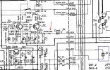
Here is the built in current limiter Re88 (red arrow). Blue box is the power LED.

7100prot.jpg

The resistor limits the amount of current that the LED uses. Without a current limiting device pretty much every bare LED would burn up.

The Welding Resistance is a poor translation. It has a 560 ohm series resistor, which would be appropriate for the voltages & current listed.

How about a link or a picture of what you used? Maybe we can help you find something that will work.

There are MANY sizes, styles and colors. Here is just a sample of thorough hole bare LED's.

 
Thank you for your help. Here is the link of what I tried to use. Note: That they are 9-12v but include the 560 ohm resistor.


The problem so far as I see it (on Amazon) is finding 9V LED without resistor included.

As I stated previously... just using an UF4004 diode (not LED obviously)... everything worked fine. Protection worked fine.
Its getting that dang red-light on the front-panel.
 
It is not the voltage it is the current that matters. You can run the LED's on many different voltages you just have to choose the correct resistor value.

You can use one that you already have by removing the in-line resistor. It is under the shrink tube where the lump is. Slice open the shrink and unsolder the resistor, then solder the wire right on the lead of the LED. Insulate it again with shrink or a wrap of tape. It should work fine. As you found out polarity matters.

led.jpg
 
I scraped off the wire in front of the 560 ohm resistor, so that the LED itself was being used, and I'd add-in some other resistors for my test.

Of course, looking at the schematic it looks like there is already that 680 resistor in series... so that is always the starting point.

560 ohm resistor added... this is the inline resistor with LED (light on). Time for click = 20-30 seconds.
470 ohm resistor added... time for click 10-12 seconds (light on).
330 ohm resistor added... time for click 6-8 seconds (light on)
100 ohm resistor added... time for click 4-5 seconds (light on)
000 ohm resistor added... time for click 2-3 seconds (light on); just using the 680 ohm resistor in the circuit.

So... the LED works in the circuit without any additional series resistor. I'll try and see how much current is going through that circuit then.

Next door neighbor (an EE) didn't see a need for any additional series resistor. It worked, but I'm still going to measure the milliamps tomorrow. He did some modelling on the circuit using Spice, and didn't understand why there were all those AC signals going through the LED.

Had to give up for now in the garage... Not used to 90 degrees yet for prolonged exposure (March 19th, 2026). Who would have thought... even in NorCal.
 
Last edited:
You need a plain red LED, green or yellow can also be used. I've duplicated this Kenwood protection circuitry and used it in other amps, and can confirm the color doesn't matter, although I haven't tried blue. However, the LED that Kenwood uses has a tapered shape and a flat face which might be hard to find. Maybe a flat faced 3mm LED would work?

Amazon is part of your problem. They sell all kinds of generic stuff from China. I would have a look on Digikey or Mouser for a suitable LED.
 
I scraped off the wire in front of the 560 ohm resistor, so that the LED itself was being used, and I'd add-in some other resistors for my test.

Of course, looking at the schematic it looks like there is already that 680 resistor in series... so that is always the starting point.

560 ohm resistor added... this is the inline resistor with LED (light on). Time for click = 20-30 seconds.
470 ohm resistor added... time for click 10-12 seconds (light on).
330 ohm resistor added... time for click 6-8 seconds (light on)
100 ohm resistor added... time for click 4-5 seconds (light on)
000 ohm resistor added... time for click 2-3 seconds (light on); just using the 680 ohm resistor in the circuit.

So... the LED works in the circuit without any additional series resistor. I'll try and see how much current is going through that circuit then.

Next door neighbor (an EE) didn't see a need for any additional series resistor. It worked, but I'm still going to measure the milliamps tomorrow. He did some modelling on the circuit using Spice, and didn't understand why there were all those AC signals going through the LED.

Had to give up for now in the garage... Not used to 90 degrees yet for prolonged exposure (March 19th, 2026). Who would have thought... even in NorCal.
The voltage drop across the LED will affect the timing of the circuit LEDS have different forward drops depending on color construction etc.

They are using the LED as a rectifier and light source.

There needs to be a reasonable amount of time before the relay clicks to prevent pops in the speaker.

Typically you see 4-5 seconds so either the 100 or 330 ohm resistor would be appropriate if you use the LED you have now.
 
Actually, more worried about the reverse breakdown voltage of an LED (typically 5V). Might try putting a UF4004 in series to see what happens 1st.
 
I settled on no resistors (i.e. took the 560 ohm resistor out of the inline LED I had), after realizing the 680 ohm RE88 resistor protected the light.

Everything now works fine EXCEPT when the system is cold (not started in say a few hours) it still takes about 10 seconds for the relay to click on instead of 4-6.

Could this be a weak QE34 issue, or maybe a tired cap. Other than a few seconds long... everything works fine.

Any pointers would be appreciated.
 
Back
Top Bottom