redpackman
Active Member
I have a Kenwood KA-8300 I love dearly, along with its little brother the KA-7100.
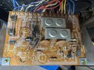
I read that the KA-8300 can often have issues on it's power supply board and in particular with resistor Rk 6 which tends to overheat and cause problems. I was also having some issues with the relay so I thought I'd go in and replace a few components there.
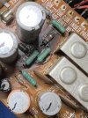
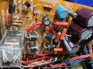
Got the relay in and then began going at the resistors. Replaced R6 with a metal film 1.8K ohm 1 watt resistor. Also got Rk1+2 with new 120 ohm 1 watt metal film resistors also Rk3 with 220 ohm 1 watt metal film resistor. Looking at the parts list in the KA-8300 service manual available on HiFi Engine I picked out four caps to replace in the same neighborhood with some nice audio Nichicons. The service manual lists two 330 uf 35w electrolytics and two 330 uf 50 w electrolytics. I ordered the Nichicon replacements.
But when I looked at the actual capacitors Ck3-6 in the power supply they were all 470 uf two 35 w and two 50w. They looked to be originals. I left them in. Three questions:
1. Are there two different builds in this model's power supply?
2. What's with the 470 uf vs 330 uf caps?
3. The Rk 6 resistor had shifted in value from the spec 1.8k to 1.136k ohms. What would that have led to now and in the future? I could see the board had been heated (discolored) but the traces hadn't been destroyed as I've seen in some other projects pictures.
With the new resistors and relay and the old caps untouched in place it really sounds nice.
Any input would be appreciated.
I read that the KA-8300 can often have issues on it's power supply board and in particular with resistor Rk 6 which tends to overheat and cause problems. I was also having some issues with the relay so I thought I'd go in and replace a few components there.
Got the relay in and then began going at the resistors. Replaced R6 with a metal film 1.8K ohm 1 watt resistor. Also got Rk1+2 with new 120 ohm 1 watt metal film resistors also Rk3 with 220 ohm 1 watt metal film resistor. Looking at the parts list in the KA-8300 service manual available on HiFi Engine I picked out four caps to replace in the same neighborhood with some nice audio Nichicons. The service manual lists two 330 uf 35w electrolytics and two 330 uf 50 w electrolytics. I ordered the Nichicon replacements.
But when I looked at the actual capacitors Ck3-6 in the power supply they were all 470 uf two 35 w and two 50w. They looked to be originals. I left them in. Three questions:
1. Are there two different builds in this model's power supply?
2. What's with the 470 uf vs 330 uf caps?
3. The Rk 6 resistor had shifted in value from the spec 1.8k to 1.136k ohms. What would that have led to now and in the future? I could see the board had been heated (discolored) but the traces hadn't been destroyed as I've seen in some other projects pictures.
With the new resistors and relay and the old caps untouched in place it really sounds nice.
Any input would be appreciated.