Hi folks, I'm brand new here and am thoroughly humbled by this forum's wealth of knowledge and kind spirit.
I'm not by any means an audiophile, nor do I have a huge desire to dive very deep on fixing this unit. BUT, I do have a masochistic tendency to not throw anything away, and I really enjoy keeping old things functioning.
After doing a little research I landed on this website being my best bet for help. So, here I am, asking for help!
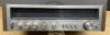
This KR-3400 came to me by way of an abandoned storage unit cleanout (among LOTS of other items in similar condition). I have a set of speakers that have been taking up space and I'd love to get this tuner (amplifier?) up and running for them.
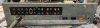
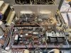
This unit has clearly been opened before as it's missing the cover's "top" screws. I gently blew out the dust with compressed air. If it has a chance at rising from the ashes, I'll go much deeper on the cleaning by following proper techniques. I have no illusions of this ever being a museum piece, but I've read quite a few user reviews and think it's worth a little time (and possible a little $).
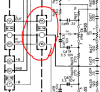
I have downloaded a copy of the service manual. The troubleshooting section doesn't seem to cover the "doesn't work at all" scenario. Honestly, I've learned over the years to seek help from those with experience prior to jumping in and making a bad situation worse.
Facts:
Thank you for looking, reading, and hopefully offering some advice!
- Calder
I'm not by any means an audiophile, nor do I have a huge desire to dive very deep on fixing this unit. BUT, I do have a masochistic tendency to not throw anything away, and I really enjoy keeping old things functioning.
After doing a little research I landed on this website being my best bet for help. So, here I am, asking for help!
This KR-3400 came to me by way of an abandoned storage unit cleanout (among LOTS of other items in similar condition). I have a set of speakers that have been taking up space and I'd love to get this tuner (amplifier?) up and running for them.
This unit has clearly been opened before as it's missing the cover's "top" screws. I gently blew out the dust with compressed air. If it has a chance at rising from the ashes, I'll go much deeper on the cleaning by following proper techniques. I have no illusions of this ever being a museum piece, but I've read quite a few user reviews and think it's worth a little time (and possible a little $).
I have downloaded a copy of the service manual. The troubleshooting section doesn't seem to cover the "doesn't work at all" scenario. Honestly, I've learned over the years to seek help from those with experience prior to jumping in and making a bad situation worse.
Facts:
- When plugged in there are no signs of life. Pressing the power button yields no sound other than the click of the switch. I have an 80s or 90s Kenwood and I'm used to it making an electrical "clunk" sound after it's power button is pressed (it died a couple years back, but that's another project/post...).
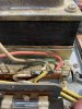
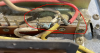
- Power is getting to the inside of the unit - tested with multimeter.
- The power switch is at least somewhat functional - the switched AC outlet functions as it should.
- It's dirty.
Thank you for looking, reading, and hopefully offering some advice!
- Calder