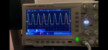
Hi all, so far I have learned a lot on this forum. I hope one of you can help me with a weird problem with a Kenwood KR-4070 receiver. I recently bought it, without knowing if it would work or not. Luckily most of the time it does and when it works it sounds really good (both on tuner and on line signal). However, after a few minutes, a loud hum comes up slowly on both channels, reaching a maximum after a few seconds and which is not affected by lowering the volume. After the unit is switched off, the hum almost always has disappeared after a few minutes. When connecting the speaker output signal to a 8 Ohm dummy load and turning up the volume of a 1000 Hz test tone, the shape of the sinus appears clean until it almost reaches clipping level. What happens next is that the sinus breaks up and only the top halve of the curve is present (see pictures before/after). This happens on both the left and right channel. I am not a technical expert, but it seems like there is some problem in one of the +/-40 power rails in the power amp module. Does anyone have a clue what may be happening here and how I may proceed? My best guess for now is to measure all power caps in the power amp module and to replace all caps that are out of spec. (BTW: the notoriously bad on/off switch seems not to be the culprit here: there is always a stable voltage coming from the main transformer). I really would like to get this Kenny working again, preferably without having to recap the whole thing… Any help is much appreciated!


You are using an out of date browser. It may not display this or other websites correctly.
You should upgrade or use an alternative browser.
You should upgrade or use an alternative browser.
Kenwood KR-4070 receiver: output problem
- Thread starter Martinvb
- Start date
-
- Tags
- distortion hum

Register to hide this ad

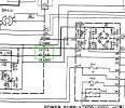
Since It is common to both channels and is not effected by the volume control I would start by checking the main filter caps. I see you have a scope. If you have two probes see if you can safely clip a probe on the B+ and B- points on the J12 and J11 points on either of the boards, or directly on the filter cap terminals that are connected to the same place.
Set you scope for AC input and see if the ripple climbs up a lot as the sound degrades. Don't forget to ground the probe clips to the chassis.
Set you scope for AC input and see if the ripple climbs up a lot as the sound degrades. Don't forget to ground the probe clips to the chassis.
Last edited:
mcdoug3721
Super Member
Looks like possible problems with negative rail power supply. Possibly main filter caps out of spec.
Last edited:
Thanks for your suggestion. That is a very good point: I will do this tomorrow and report back.Since It is common to both channels and is not effected by the volume control I would start by checking the main filter caps. I see you have a scope. If you have two probes see if you can safely clip a prob on the B+ and B- points on J12 and J11 points on either of the boards Or directly on the filter cap terminals that are connected to the same place.
Set you scope for A/C input and see if the ripple climbs up a lot as the sound degrades. Don't forget to probe ground clips to the chassis.
View attachment 3326007
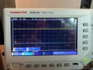
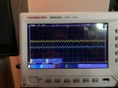
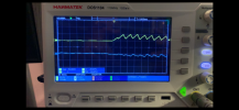
@mrk229 So the story continues… on idle, B-and B+ measure 80.0V, using a multimeter. As I am relatively new with my scope, I let it calibrate the signals coming from B- and B+ We see a shallow 50 Hz sawtooth, equal but inverted on both channels (see picture). Isn’t that what you would expect? When turning up the volume (1000Hz) the sawtooth signals gets stronger, while the measured voltage at B-/+ drops a bit. At 73.5 volts (+/- volume halfway) voltage drops suddenly but immediately comes up again to 80V. Could this be a kind of ‘protection mode’? What do you think, should I measure the power caps next?Thanks for your suggestion. That is a very good point: I will do this tomorrow and report back.
Attachments
Last edited:
I appears you have the scope set for DC We want to concentrate on the AC (Sawtooth) values.
Set the scope input for AC, and then we should clearly see the amplitude of the AC signal that is on the B+ and B- supply lines
That appears to be quite a bit of AC ripple when under load which is indicative of bad filter caps.
Set the scope input for AC, and then we should clearly see the amplitude of the AC signal that is on the B+ and B- supply lines
That appears to be quite a bit of AC ripple when under load which is indicative of bad filter caps.
Today I did the same measurements (1000Hz test tone, again measurement on B-/+), but this time with the scope in AC mode. Pictures show a kinda symmetrical sawtooth voltage pattern, with an increasing amplitude when volume goes up. Again, when volume gets too high, the voltage breaks down. As suggested, I took out both power caps (7500uF, 50V each) and measured a capacity of less than 50% in both (see pictures). This looks really bad, doesn’t it? I have already been looking around, but it seems hard to find exact replacement caps. How strict should you be in terms of capacity, you think? Your help is much appreciated!I appears you have the scope set for DC We want to concentrate on the AC (Sawtooth) values.
Set the scope input for AC, and then we should clearly see the amplitude of the AC signal that is on the B+ and B- supply lines
That appears to be quite a bit of AC ripple when under load which is indicative of bad filter caps.
Attachments
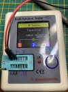
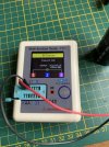
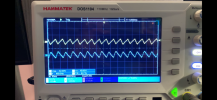
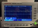
Yes that is what bad filter caps look like. Finding them is a bit of a black art in the parametric search on Dkey or Mouser.
You should be safe with 10,000uF, I would look for 63 volt caps. Most new caps seem to error on the low side of the stated tolerances, most are + or - 20%.
It appears the current caps are mounted on a PC board. How many terminals do they have? How far apart are the terminals? And what are the dimensions of the current caps?
Here are some that may or may not be exact fit, we can possibly narrow it down with the dimensions and terminal info. (picture of the bottom of the pc board would be good)
You should be safe with 10,000uF, I would look for 63 volt caps. Most new caps seem to error on the low side of the stated tolerances, most are + or - 20%.
It appears the current caps are mounted on a PC board. How many terminals do they have? How far apart are the terminals? And what are the dimensions of the current caps?
Here are some that may or may not be exact fit, we can possibly narrow it down with the dimensions and terminal info. (picture of the bottom of the pc board would be good)
Last edited:
Wow, you are fast, thanks for your reply. The Elco’s have 3 pins, one seems for extra grip on the PCB. The distance between + and - poles is 1.5 cm, but the PCB also takes caps with 1 cm distance.Yes that is what bad filter caps look like. Finding them is a bit of a black art in the parametric search on Dkey or mouser.
You should be safe with 10,000uF, I would look for 63 volt caps. Most new caps seem to error on the low side of the stated tolerances, most are + or minus 20%.
It appears the current caps are mounted on a PC board. How many terminals do they have? How far apart are the terminals? And what are the dimensions of the current caps?
Here are some that may or may not be exact fit, we can possibly narrow it down with the dimensions and terminal info. (picture of the bottom of the pc board would be good)
Attachments
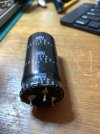
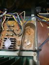
Nice, then any of the caps listed will fit the pin holes as the pin spacing is 10mm. 3 Pin caps are almost impossible to find and yes the extra pin is for mechanical stability.
I see it has a pseudo clamp/shield type thingy. What diameter are the old ones? The caps I listed are two different diameters, and there are other choices as well.
I think I would glue the new ones in as well. I typically use E-6000 for that.
I see it has a pseudo clamp/shield type thingy. What diameter are the old ones? The caps I listed are two different diameters, and there are other choices as well.
I think I would glue the new ones in as well. I typically use E-6000 for that.
Caps are 3cm in diameter and fit tight in the metal shield, so anything larger than 3cm will not work. I may have found cap replacement candidates on Amazon, so I might go with these first and see if this does the trick. Is E6000 sticky stuff that does not melt with high temperatures. Then I should try to get some of that as well. Your advise has been very valuable: I will report back here when the repair is done. Kind regards, MartinNice, then any of the caps listed will fit the pin holes as the pin spacing is 10mm. 3 Pin caps are almost impossible to find and yes the extra pin is for mechanical stability.
I see it has a pseudo clamp/shield type thingy. What diameter are the old ones? The caps I listed are two different diameters, and there are other choices as well.
I think I would glue the new ones in as well. I typically use E-6000 for that.
mcdoug3721
Super Member
I would recommend buying the caps and electronic components from Mouser, Digikey or another reputable electronics distributor. Authenticity and reliability are questionable for many of the Amazon components. Just make sure you order 30mm diameter. Kemet, Nichicon and CDE would typically be the recommended brands. The link below shows what is available at Digikey in 8200uf and 10000uf 63V with 30mm width and 10mm lead spacing. Not sure what height works best for the 4070.
https://www.digikey.com/en/products/filter/aluminum-electrolytic-capacitors/58?s=N4IgjCBcoCwGxVAYygMwIYBsDOBTANCAPZQDaIMArAEzUAcIAuoQA4AuUIAymwE4CWAOwDmIAL6FKABgbQQKSBhwFiZENTAwAzA2Yh2nHgJHjC1KTACcieWix5CJSOTrmpAAgCtAMRCEwUoEePkysHJAgAKqC-GwA8qgAsrjo2ACuvLim6lIA7NZyCkoOqs4gcFruAGqh+uFRMfFJKemZ2QC0EIV2yo5qWjp+IFqW1oRWWkwSIO3UNgp8aSpO5JRThO0FyFCLy2oQjGLTc2W4mLhIfESYAJ5s-CiHQA
https://www.digikey.com/en/products/filter/aluminum-electrolytic-capacitors/58?s=N4IgjCBcoCwGxVAYygMwIYBsDOBTANCAPZQDaIMArAEzUAcIAuoQA4AuUIAymwE4CWAOwDmIAL6FKABgbQQKSBhwFiZENTAwAzA2Yh2nHgJHjC1KTACcieWix5CJSOTrmpAAgCtAMRCEwUoEePkysHJAgAKqC-GwA8qgAsrjo2ACuvLim6lIA7NZyCkoOqs4gcFruAGqh+uFRMfFJKemZ2QC0EIV2yo5qWjp+IFqW1oRWWkwSIO3UNgp8aSpO5JRThO0FyFCLy2oQjGLTc2W4mLhIfESYAJ5s-CiHQA
Martin,Caps are 3cm in diameter and fit tight in the metal shield, so anything larger than 3cm will not work. I may have found cap replacement candidates on Amazon, so I might go with these first and see if this does the trick. Is E6000 sticky stuff that does not melt with high temperatures. Then I should try to get some of that as well. Your advise has been very valuable: I will report back here when the repair is done. Kind regards, Martin
Yep I am with @mcdoug3721 on buying components from reputable sources. The amazon seller may be offering a legit brand name part, or they may not. I would not buy any off brand stuff at all but ultimately the choice is yours.
@mcdoug3721 @mrk229 I appreciate your advice and think you are right. I went over some of the reviews of the offered items and there were several customers complaining about the quality (particularly ‘new’ caps being seriously out of spec). Will update on this project soon.Martin,
Yep I am with @mcdoug3721 on buying components from reputable sources. The amazon seller may be offering a legit brand name part, or they may not. I would not buy any off brand stuff at all but ultimately the choice is yours.
Yes by all means keep us in the loop.
Personal Preference here. I have used this series of caps in the past, and this is the one I would pick : https://www.digikey.com/short/452czcnq
Generally you can't go wrong with Nichicon as well.
Personal Preference here. I have used this series of caps in the past, and this is the one I would pick : https://www.digikey.com/short/452czcnq
Generally you can't go wrong with Nichicon as well.
Last edited:
@mrk229 New caps have arrived and were soldered in place without difficulty: so far, this has resolved all the audible distortion that I experienced previously. Output power is about 50% higher as rated by Kenwood (58 vs. 40 WPC), but is already reached at 50% of output volume (instead of approximately 70% with the old caps). I suppose it is not a good idea to stress the old amp more than needed…. Anyway, thanks for all good advice and support guys! Great community here at Audiokarma .
mcdoug3721
Super Member
How did you measure the output? What was the amplitude of the input signal?
Glad it is working. I am not surprised that you are getting more power than specified. Kenwood did not say what the AC line voltage was when measured, I bet it was lower than what comes out of the wall in most homes today. A higher input voltage gives you a higher voltage on the output transistors which can translate to a higher power output.@mrk229 New caps have arrived and were soldered in place without difficulty: so far, this has resolved all the audible distortion that I experienced previously. Output power is about 50% higher as rated by Kenwood (58 vs. 40 WPC), but is already reached at 50% of output volume (instead of approximately 70% with the old caps). I suppose it is not a good idea to stress the old amp more than needed…. Anyway, thanks for all good advice and support guys! Great community here at Audiokarma .
I don't think you would see 18 more watts though. How did you determine the output power?
mcdoug3721
Super Member
150mv was typical AUX input sensitivity for Kenwood receivers of that year. 500mv would probably clip at 50% volume pot. Anything over 45 watts is very good. Nothing to be concerned about and seems to be back to good health.
Last edited: