Swaler61
New Member
Hey all,
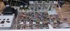
I'm working on a new to me Kenwood KR-4140, and it is in overall pretty good shape, and so far works pretty well and really liking the tone!
For background, I'm a career EE, but haven't worked on a lot of old solid state circuitry, as I'm more of a guitar amp and old radio guy. Some jukebox work thrown in, too.
Meanwhile, some observations...
Overall, I am a fan of replacing electrolytics with films where possible, esp. in the signal path, but for now I'm going to leave this unit as-is since it sounds so good.
Whoa, noted a LOT of heat coming off the main heat sink, even when the receiver was sitting idle, and have two observations on that: transistor mounting and incorrect idle current setting.
One thing I noticed on the 2SD155 output transistors: they were mounted dry (no thermal compound), with 4-5 layers of what looked like some kind of plastic insulators, they did not look like mica. I have no idea if these output transistors are original, but interesting that they lasted this long.
For future posterity, and at the risk that this has already been covered elsewhere, I will now interject here with some recommendations on mounting TO packages onto heat sinks. These observations come out of my design work on power transistor and heat management. In general:
On the KR-4140 in question, did exactly the items above. First removed the sink from the chassis and checked for flatness with a file, on both the sink and the transistors. I put in an order for some mica insulators for TO-66 packages (I didn't have any), and in the meantime used a single layer of the old insulators and remounted them with thermal compound. As above, I checked to make sure no transistors were shorted to the sink before powering back up. When the mica ones come in, I'll install them and close it up.
Between the idle current being set, and better mounting, this unit is running WAY cooler. Like I said am really liking the tone of this one!

Kind of excited to see how the newer LED fuselamps will work, have never tried them before, and need to rig up an LED for a stereo light, so we'll see what happens. To be continued...
Rock on
Scottie
I'm working on a new to me Kenwood KR-4140, and it is in overall pretty good shape, and so far works pretty well and really liking the tone!
For background, I'm a career EE, but haven't worked on a lot of old solid state circuitry, as I'm more of a guitar amp and old radio guy. Some jukebox work thrown in, too.
Meanwhile, some observations...
Overall, I am a fan of replacing electrolytics with films where possible, esp. in the signal path, but for now I'm going to leave this unit as-is since it sounds so good.
- It's a matter of debate regarding changing out all of the ~53 year-old ecaps, and I'll leave that debate for other threads.
- Same observation regarding the 2SC458s here, they sound good and are working well, am going to leave them for now.
Whoa, noted a LOT of heat coming off the main heat sink, even when the receiver was sitting idle, and have two observations on that: transistor mounting and incorrect idle current setting.
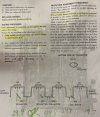
- Checked and reset the idle bias current on this unit and it went pretty well. However, the old trimmers used in this are really glitchy. While I have them set in the ballpark, I'm going to try replacing them with multiturn trimmers as an experiment. They are on order.
- After getting the idle current set at least closer to where it should be, I noted right away that there is a lot less heat generation from the output transistors. Nice.
One thing I noticed on the 2SD155 output transistors: they were mounted dry (no thermal compound), with 4-5 layers of what looked like some kind of plastic insulators, they did not look like mica. I have no idea if these output transistors are original, but interesting that they lasted this long.
For future posterity, and at the risk that this has already been covered elsewhere, I will now interject here with some recommendations on mounting TO packages onto heat sinks. These observations come out of my design work on power transistor and heat management. In general:
- Before mounting the transistors, make sure the surface where your transistor is mounted is flat as possible to create a clean "mechanical interface" between the TO and the sink. Also check that the surface of the transistor itself is flat, too, they can sometimes have burrs that can pierce the insulator or cause a gap that can keep heat from flowing as well as it could.
- Whenever possible, always use some thermal compound when mounting to a heat sink. It really helps to get that heat flowing into the heat sink to spread the heat out. Yeah, thermal grease is messy to deal with, but we're not in a production plant working by the hour. Take your time, this is a hobby, right? Don't overdo it, use just enough so that a little pushes out after being tightened.
- When you're using an insulator (most of the time), use a single insulator and put compound on both sides. I recommend mica rather than plastic or sil-pad insulators. Sil-pads can work, but for long-term use I would still lean toward mica and compound, esp. for vintage gear.
- Hard to define this: snug the mounting screws down, but don't go crazy. If you over tighten them, you could warp the transistor or short it to the sink by crushing the insulator. Don't obsess on it, but if you can, go back and check tightness after a few heating and cooling cycles.
- After you've tightened it down, and BEFORE powering up, use an ohmmeter to make sure there isn't a dead short between the TO and the sink. It happens sometimes, so remove the device and recheck your work. Maybe a burr you missed on the sink or the transistor package? A metal filing swimming in the compound? It happens, wipe it off, check it and redo it. Recheck with the ohmmeter before moving on.
On the KR-4140 in question, did exactly the items above. First removed the sink from the chassis and checked for flatness with a file, on both the sink and the transistors. I put in an order for some mica insulators for TO-66 packages (I didn't have any), and in the meantime used a single layer of the old insulators and remounted them with thermal compound. As above, I checked to make sure no transistors were shorted to the sink before powering back up. When the mica ones come in, I'll install them and close it up.
Between the idle current being set, and better mounting, this unit is running WAY cooler. Like I said am really liking the tone of this one!
Kind of excited to see how the newer LED fuselamps will work, have never tried them before, and need to rig up an LED for a stereo light, so we'll see what happens. To be continued...
Rock on
Scottie
Last edited: