


MBuras
Restoration is an Addiction
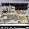
While I was working on a basket case KR-4400 I noticed there didn't seem to be much info on the forum about this model. This thread is just meant to document the components I found inside my receiver.
There weren't many variations from the service manual other than the main amp board. Apparently at some point Kenwood changed the board model. It wasn't especially easy to track down as all the AK links were really old and not working anymore. Here is one link, there are others.
https://www.scribd.com/document/476171888/Kenwood-KR-4400-KR-5400-KA-4600-Service-Manual-Supplement
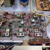
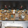
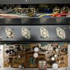
The following is what I found on the boards. Mostly documented electrolytic caps, not films. Unless noted they all agree with the service manual.
KR-4400
Serial #212297
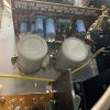
Main Filters:
C302/C303 4700uf/35v [measure 35mm wide x 50mm tall] [also note the hole in the frame is only a slot so capacitor base sits on frame]
Lights:
I just bought some LED wedge lamps and soldered those in place of the originals. Getting the rubber grommets out of the housing without tearing them was a challenge, as was getting the original bulbs out of the grommet without breaking them.
Power Supply X00-1460-10
CK03 220uf/35v
CK04 100uf/35v
CK05 220uf/16v
CK06 100uf/16v
CK07 100uf/16v
CK09 470uf/16v
DK01-DK04 U0-5B rectifier diodes
DK05 DZ-140 14v zener
DK06 YZ-140 14v zener
DK07 W0-6B diode
Fuse is a 2A glass fuse - fast blow
Tuner X05-1110-00
CG32 100uf/16v
CG40 100uf/3v [seemed to be a manual misprint - actually on board was 220uf/6.3v]
CG45 1uf/50v
CG46 4.7uf/25v
CG52 10uf/25v
CG55 1uf/50v
CG56 10uf/25v
CG61 10uf/25v
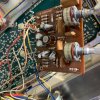
Main Amp X07-1350-10 [as noted above this is different from the OG service manual which specs X07-1280-11]
CE03/CE04 1uf/50v [on this board variation there are extra holes and plenty of room for a large film cap]
CE05/CE06 10uf/25v [note: CE06 the board screen print polarity is reversed]
CE11/CE12 220uf/16v
CE13/CE14 47uf/50v
CE17-CE20 47uf/6.3v [10v caps were actually installed on board]
CE23 220uf/50v
CE24 1uf/50v
CE25 100uf/16v [note: this is a BP cap!]
CE26 100uf/25v
QE01-QE04 2SA620 [differential pairs]
QE05/QE06 2SC1451 [general consensus as failure prone]
DE01-DE04 1S2076 diode
DE05 YZ-140 14v zener
DE06/DE07 1S2076 diode
DE08 EQA01-08 8.2v zener
RL01 MY4-02-DC24 [not available due to supply so I just burnished the contacts]
Preamp X08-1270-00
CD01/CD02 3.3uf/10v [tantalum gumdrops]
CD03/CD04 33uf/6.3v [these were actually 10v on board]
CD05/CD06 0.22uf film [these were actually 1uf/50v electrolytics on board] [there are extra holes and plenty of room for a large film cap] [no board printing for polarity - if using electrolytics the negative faces the outside edge of the board]
CD07/CD08 47uf/16v
Tone Amp X11-1200-01
CI01/CI02 1uf/25v
CI03/CI04 10uf/25v
CI05/CI06 4.7uf/10v [these were actually 35v on board] [no polarity markings on board - CI05 negative faces CI03 and CI06 negative faces CI04]
CI15/CI16 100uf/10v
Also of note is a single 1uf/50v cap across two terminals on the selector switch. Not easy to get at and may go unnoticed without a detailed examination. Couldn't find it in the SM.
And because I always need a refresher when working on Kenwoods, here's how to decode their transistor board markings.
dot = collector
line crossing circle = base
line stopping at circle = emitter
There weren't many variations from the service manual other than the main amp board. Apparently at some point Kenwood changed the board model. It wasn't especially easy to track down as all the AK links were really old and not working anymore. Here is one link, there are others.
https://www.scribd.com/document/476171888/Kenwood-KR-4400-KR-5400-KA-4600-Service-Manual-Supplement
The following is what I found on the boards. Mostly documented electrolytic caps, not films. Unless noted they all agree with the service manual.
KR-4400
Serial #212297
Main Filters:
C302/C303 4700uf/35v [measure 35mm wide x 50mm tall] [also note the hole in the frame is only a slot so capacitor base sits on frame]
Lights:
I just bought some LED wedge lamps and soldered those in place of the originals. Getting the rubber grommets out of the housing without tearing them was a challenge, as was getting the original bulbs out of the grommet without breaking them.
Power Supply X00-1460-10
CK03 220uf/35v
CK04 100uf/35v
CK05 220uf/16v
CK06 100uf/16v
CK07 100uf/16v
CK09 470uf/16v
DK01-DK04 U0-5B rectifier diodes
DK05 DZ-140 14v zener
DK06 YZ-140 14v zener
DK07 W0-6B diode
Fuse is a 2A glass fuse - fast blow
Tuner X05-1110-00
CG32 100uf/16v
CG40 100uf/3v [seemed to be a manual misprint - actually on board was 220uf/6.3v]
CG45 1uf/50v
CG46 4.7uf/25v
CG52 10uf/25v
CG55 1uf/50v
CG56 10uf/25v
CG61 10uf/25v
Main Amp X07-1350-10 [as noted above this is different from the OG service manual which specs X07-1280-11]
CE03/CE04 1uf/50v [on this board variation there are extra holes and plenty of room for a large film cap]
CE05/CE06 10uf/25v [note: CE06 the board screen print polarity is reversed]
CE11/CE12 220uf/16v
CE13/CE14 47uf/50v
CE17-CE20 47uf/6.3v [10v caps were actually installed on board]
CE23 220uf/50v
CE24 1uf/50v
CE25 100uf/16v [note: this is a BP cap!]
CE26 100uf/25v
QE01-QE04 2SA620 [differential pairs]
QE05/QE06 2SC1451 [general consensus as failure prone]
DE01-DE04 1S2076 diode
DE05 YZ-140 14v zener
DE06/DE07 1S2076 diode
DE08 EQA01-08 8.2v zener
RL01 MY4-02-DC24 [not available due to supply so I just burnished the contacts]
Preamp X08-1270-00
CD01/CD02 3.3uf/10v [tantalum gumdrops]
CD03/CD04 33uf/6.3v [these were actually 10v on board]
CD05/CD06 0.22uf film [these were actually 1uf/50v electrolytics on board] [there are extra holes and plenty of room for a large film cap] [no board printing for polarity - if using electrolytics the negative faces the outside edge of the board]
CD07/CD08 47uf/16v
Tone Amp X11-1200-01
CI01/CI02 1uf/25v
CI03/CI04 10uf/25v
CI05/CI06 4.7uf/10v [these were actually 35v on board] [no polarity markings on board - CI05 negative faces CI03 and CI06 negative faces CI04]
CI15/CI16 100uf/10v
Also of note is a single 1uf/50v cap across two terminals on the selector switch. Not easy to get at and may go unnoticed without a detailed examination. Couldn't find it in the SM.
And because I always need a refresher when working on Kenwoods, here's how to decode their transistor board markings.
dot = collector
line crossing circle = base
line stopping at circle = emitter
