• The move to the new server is done. There are some software and database maintenance updates in process. This has us passing the hat around to help out. We appreciate any donations. Seriously, even a dollar helps. The payment page may be found here - https://www.audiokarma.org/support.html

Kenwood kr-5200 bias adjustment and protection relay

Oldsansui441

Super Member
Hi, I have a Kenwood kr-5200 here that required a fair amount of work to get up and running.

A previous owner recapped main amp board and then must have lost interest. I have replaced all transistors and some resistors on main amp and replaced op transistors also with on semi mj15003g's.
I also had to replace a couple of other transistors, one for driving fm stereo light and one for tuning meter. I replaced globes as well and reflowed tone board cracked soldered joints.

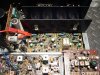
My main question is in regard to setting bias. In the attached photo l have shown where l took the measurement between outer leg of emitter resistor and earth (same on other channel). Can any of you Kenwood experts please confirm if this is correct as the service manual infers checking ACROSS emitter resistor. This is the only way l can get a correct reading and adjust to factory spec of 20mV. I have ran receiver for a approx 20 mins so far and heatsink was a nice warm, even temp across both sides.

Also the protection relay engages very quickly, approx 2 seconds after power on, is this normal on this model?

Appreciate any help, thanks.
 

Attachments
  • P1020494.JPG
    P1020494.JPG
    131.2 KB · Views: 147
  • Kenwood kr-5200 bias adjustment.png
    Kenwood kr-5200 bias adjustment.png
    112.8 KB · Views: 141
Last edited:
Register to hide this ad
I'm certainly not a Kenwood expert, but the bias adjustment diagram in the Kenwood manual is indeed slightly confusing - it shows the emitter resistor that's being tested as though one end of it is connected to ground. That's not actually the case according to the KR-5200 schematic I'm looking at - as the main amp uses +ve & -ve supply rails (+/- B). The text however seems correct "connect the voltmeter across the emitter resistor of power transistors".

Your photo seems to show the red lead of the voltmeter connected to the Qe12(emitter) end of Re30 (one of the left channel emitter resistors), and the black lead connected to the chassis (ground). I don't believe the chassis would be the correct location for the black meter lead, as the emitter resistors are not connected to ground.

As far as I can see, the simplest, and probably least confusing way to check would be to just put one meter lead on each end of the emitter resistor being tested - with all the controls 'zero'ed', no speakers, and no input, you're then simply measuring the voltage drop across the emitter resistor, which the manual states should be adjusted to 20mV. The 4 emitter resistors are Re29 & Re31 (Right channel), and Re30 & Re32 (Left channel). If you have any mini-grabber leads, it'll be a lot easier (and safer) than the crocodile clips.
 
Last edited:
manual says across one emitter resistor .
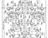
the small schematic you posted is not correct for the 5200 ..
i looked at relay circuit and .. ce16 may have something to do with it ..check the correct value is installed .schem shows 33uf 50v .
 
manual says across one emitter resistor

Sorry - I didn't mean to imply otherwise - I simply listed the 4 separate emitter resistors. Personally, I'd just use Re31 for one channel, and Re32 for the other.

the small schematic you posted is not correct for the 5200 ..
i looked at relay circuit and .. ce16 may have something to do with it ..check the correct value is installed .schem shows 33uf 50v .

The small schematic diagram the OP posted is actually from the service manual (well, it's in the copy on hifiengine.com), but I agree, it's wrong for the KR-5200

Ce16 indeed looks like the cap responsible for relay timing. If it still measures at +/- 33uF, then I suspect a 2 second relay delay was / is 'normal'.
 
I'm certainly not a Kenwood expert, but the bias adjustment diagram in the Kenwood manual is indeed slightly confusing - it shows the emitter resistor that's being tested as though one end of it is connected to ground. That's not actually the case according to the KR-5200 schematic I'm looking at - as the main amp uses +ve & -ve supply rails (+/- B). The text however seems correct "connect the voltmeter across the emitter resistor of power transistors".

Thanks for your reply, yes that is what confused me, you are correct it shows one end connected to ground, l will try one lead on each end of emitter resistors again, but l couldn't achieve a reading here before.
Good call on the mini grabbers, l do have these and regularly use them, should have used them for this also.

the small schematic you posted is not correct for the 5200 ..
i looked at relay circuit and .. ce16 may have something to do with it ..check the correct value is installed .schem shows 33uf 50v

Thanks for your reply, sorry about the small image, this is out of the kr-5200 service manual, so may be a mistake?
I will check value of ce16 for sure.
 
i think its kenwoods poor excuse for an example showing an emitter resistor grounded . if it were a cap coupled amp with a single power supply this would be correct .but not correct in this case .
 
Move your clip from the chassis to directly on the emitter resistor lead. Problem solved.
 
Thanks, l did try that initially but will try again after l make more repairs. Today it started burning up resistor re40 for some reason, was fine yesterday, all l have done since is replace ce16 cap with correct value.

Last guy fitted a 47uF in place of a 33uF like the guys suggested, although l am not 100% confident the service manual is correct for this kr-5200 as there appears to be an up to and from serial number and l can't find the later version. I have noticed some resistor values are different to service manual and power supply boards are also different.

Don't see how ce16 would at all relate to re40, ahh well l will have to investigate further. One fuse also open.
 
Would anyone have the kr-5200 schematic that includes the later X00-1290-10 power supply board? I have a few voltages that are questionable including 8.4v to tuner board instead of 13.5v.
I have looked everywhere for the later schematic online but none are readable in regard to pinout voltages.
Any help appreciated, thanks.
 
Thanks, l did try that initially but will try again after l make more repairs. Today it started burning up resistor re40 for some reason, was fine yesterday, all l have done since is replace ce16 cap with correct value.

Last guy fitted a 47uF in place of a 33uF like the guys suggested, although l am not 100% confident the service manual is correct for this kr-5200 as there appears to be an up to and from serial number and l can't find the later version. I have noticed some resistor values are different to service manual and power supply boards are also different.

Don't see how ce16 would at all relate to re40, ahh well l will have to investigate further. One fuse also open.
This have early and late version high serial number and service bulletins too maybe correct manual help! ; - ) Cheap too for complete data only $25! ; - )
http://www.stereomanuals.com/man/rep/kenwood/kenwood_manuals_kr-4010_xx.htm
Kenwood KR-5200 Receiver Service Manual We have also added schematics for units with Serial # 720,001 and above. G17 KENKR5200-SM 82 total pages (12 intentionally blank) including (4) 11in x 17in schematic inserts, and (2) Tech Bulletins, constructed as the original including numerous 11in x 17in folded /trimmed pullout pages, card stock covers, neatly assembled with 5 staples and fiber reinforced taped spine. The schematic pages in the original contains small print. So in addition to making normally, we added enlarged versions as 11in x 17in inserts. Overall quality is Very Good to Excellent.

Hope you find issue! ; - )
JJ
 
Hi JJ, thanks heaps for checking that out for me, that is really good to know. I am still working on this one, the Kenwood schematics are fairly basic compared to some of the other manufacturers in that they don't provide voltages for transistors etc, makes things a little harder.
 
Hi JJ, thanks heaps for checking that out for me, that is really good to know. I am still working on this one, the Kenwood schematics are fairly basic compared to some of the other manufacturers in that they don't provide voltages for transistors etc, makes things a little harder.
I use that company manuals best there is for reprints! ; - )
JJ
 
I have finally fixed the Kenwood after chasing my tail on this for hours. The voltage supply problems ending up being caused by Dk7 zener diode on X00-1290-10, l had previously checked this and all other components on power supply board many times, Dk7 tested fine with diode function on my meter but l ended up just replacing this as a precaution and now all voltages are good. (It's frustrating when all components you check test good but you know problem exists). Amazing how much better things work with 14v instead of 8.4v, haha.

I pulled all new transistors on left channel to check for shorts as fuse was previously blowing but all components were ok so must have been power supply issues causing intermittant high current draws.
As l mentioned above l replaced Ce16 on the main amp with the correct 33uF cap and now the relay turn on time is a little longer.
As to the erroneous bias readings l was originally getting ACROSS emitter resistors, l cannot actually explain this as now l can obtain reading and set across these perfectly.

Thanks to everyone for your help, Cheers.
 

Attachments

Hi, after running the receiver for a while l noticed left channel was running noticably warmer than right.
I found stv-3 (De3) for left channel was intermittantly faulty. l replaced this with 3 1n4007's and also replaced the trimmers with 100ohm Bournes multi turns.
I found l had to replace re19 (4.8k) resistor with a 10k to bring bias back into adjustable range for that channel. Was about 10-15mV high before resistor change, but trim pot was adjusted fully to lowest impedance.

Is this an acceptable measure with my altering of that resistor value? I have been running receiver for a few hours now and seems to be running fine, heatsink and all four outputs seem to be relatively same temp.

Thanks again for any help.

upload_2016-10-25_15-0-13.png
 
I found stv-3 (De3) for left channel was intermittantly faulty.
That's a pretty unusual failure. How did you determine that the STV device was the problem?

And, these STV's used are the axial devices? Not the radial devices?

The only thing I'd worry about is starving the driver transistors of current at high outputs. I'd want to look at the output at full power on a scope and see that it looks good.
 
The only way l realised was l ran the unit enough to get up to a certain temp, then l noticed the heatsink was uneven, so l quickly checked bias again and it was intermittantly all over the place on that channel.
I then swapped the stv-3's from side to side and the problem went with it.
Yes they are the axial types, l do like to keep things as original as possible but wasn't keen on spending $60.00 (inc postage) on an original stv-3, this thing already owes me too much, haha.

Thanks Echowars, l read through all of your info on the stv subject before l completed this repair, l know you didn't specify 1n4007's but that is what l had on hand, also l think the stv-3h was mostly mentioned not the stv-3, seems to work quiet well though, l know from a cold start the bias seems to ramp at the same rate as the other channel.

I am going to have to answer my own stupid question in regards to the resistor l replaced, l checked all resistors on this board a couple of weeks ago and they all checked ok.
Now it seems the reason Re19 brought circuit back to adjustability was because Re17 has now gone slightly off spec and allowing 30v to pass as opposed to other channels 27-28v.
I found q7 and q8 bases were both getting 1.1v, so all good.
 
Last edited:
Back
Top Bottom