• The move to the new server is done. There are some software and database maintenance updates in process. This has us passing the hat around to help out. We appreciate any donations. Seriously, even a dollar helps. The payment page may be found here - https://www.audiokarma.org/support.html

Kenwood KR-5200 no stereo in FM

I think you got the leads improperly identified.
14.2 volts collector
2.1 volts base
1.5 volts emitter
would be exactly as expected.

When trying to listen to stereo, you get only mono, but you get it out of both channels, correct?

I am suspecting a bad Lc4. Lots of turns of very fine wire - not unusual to have these fail. Would be best to have an Oscilloscope, but let's see what we can do with your DMM set to the AC range. If you have a scope, let me know, otherwise set the DMM to AC, and connect it across the primary of Lc4 (in parallel with Cc8. What do you get for an AC voltage?.
 
When trying to listen to FM in stereo mode, sound is only coming from right side. When I turn the balance all the way to the left, you can barely hear it. All other such as phono, aux1and2 it are in stereo. Like I said, I am just learning and do have an oscilloscope but haven’t learned to use it yet. I will get back with you on the a/c voltage across Lc4
 
That changes things a bit - may be easier to troubleshoot.

Screenshot 2022-03-05 122809.jpg Screenshot 2022-03-05 123013.jpg
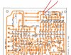
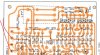
Locate the LPF (Lc5). Add a jumper between the two indicated points. Do you now get audio out of both channels?
 
Remove the jumper. Take a close look at the runs/solder connections around Rc29, Rc31, Rc33, and the LPF terminals. Reflow anything suspicious.

If that doesn't fix it, may have an open LPF. One more jumper to try. Add a jumper between the input and output of the left side of the LPF - This would be from Rc29 to Rc31/Rc33.
 
All runs/solder joints look good. I put a jumper from Rc29 to Rc31 and I’m getting sound out of both sides.
 
So your left side LPF is open. Chances are not too good for you to find a replacement. The LPF removes any remaining 19 KHz from the audio and I've been told suppresses interaction of a cassette tape bias oscillators. I'd suggest you just leave that jumper in.
 
Thank you so much for all of your help! I think I learned a thing or two as well. If you run across a replacement, let me know. I will leave the jumper in as you suggest. Thanks again!
 
Best bet would probably to watch ebay for a pullout MPX board. (X04-1010-10). Don't see anything there now.
 
Best bet would probably to watch ebay for a pullout MPX board. (X04-1010-10). Don't see anything there now.
Hi Ylli, I’ve been reading this thread and hoped you might know if I can follow the same procedures on my Kenwood KR-6400? Issues, stereo indication not working (bulb operation verified), no multiplexing that I can tell, fm signal meter not working in fm (it does however illuminate). I’ve been working my way through the signal meter circuit:
pin 3 13.8v
R22 2.32v
R41 .15v
R57 -0.008 on high side of resistor

Novice here…but committed to seeing this through.
 
Yes, on AM, signal meter is illuminated and working. I forgot to mention, on FM, I'm using a 300 Ohm antenna and the stations come in strong. Also, on AM, the tuning meter is not illuminated but IS when on FM (this could be normal operation?). Neither AM nor FM drive any tuning needle movement.
 
The illumination you see is normal - Signal meter lit up on AM and FM, tuning meter lit up on FM only. AM mode does not drive the tuning meter.

To summarize:
AM is working normally, with active signal strength meter.
FM is receiving stations, but no meter movement or stereo decoding. Is it receiving just the stronger stations or does it also receive weaker signals? With no signal strength or tuning meter movement, that would lead me to believe there is a loss of gain in the front end/IF section. But if you can receive weaker signal, that is inconsistent with that possible problem.

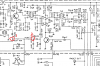
Let's make a couple of voltage measurements. Connect your voltmeter to the end of Rg57 that is also connected to the anode of Dg10, labeled "1" in the attached. Tune to the strongest AM station you can find and note the voltage and the % of signal meter deflection. (e.g. 0.78 volts, 75%). Move the voltmeter to the end of Rg56 that is also connected to the anode of Dg13, labeled "2" in the attached. Tune to the strongest FM station you can find and note the voltage and the % meter deflection as you did with the AM signal.

Screenshot 2022-05-25 104100.png
 
The illumination you see is normal - Signal meter lit up on AM and FM, tuning meter lit up on FM only. AM mode does not drive the tuning meter.

To summarize:
AM is working normally, with active signal strength meter.
FM is receiving stations, but no meter movement or stereo decoding. Is it receiving just the stronger stations or does it also receive weaker signals? With no signal strength or tuning meter movement, that would lead me to believe there is a loss of gain in the front end/IF section. But if you can receive weaker signal, that is inconsistent with that possible problem.

Let's make a couple of voltage measurements. Connect your voltmeter to the end of Rg57 that is also connected to the anode of Dg10, labeled "1" in the attached. Tune to the strongest AM station you can find and note the voltage and the % of signal meter deflection. (e.g. 0.78 volts, 75%). Move the voltmeter to the end of Rg56 that is also connected to the anode of Dg13, labeled "2" in the attached. Tune to the strongest FM station you can find and note the voltage and the % meter deflection as you did with the AM signal.

View attachment 2576216
I think it’s a fair statement that only the strong stations are coming through. I can now get the meter moving slightly, up to 1.75, but with static.
R56-D13 = 0.025v
R57-D18 = 0.2v
R41-D10 = 0.08v
When I take readings on the best sounding (meter at 1) station…in the same order as above.
-0.001v
-0.013v
0.136v
Photo attached.

thanks again for your help!
 

Attachments

  • EC79A63D-C1AF-4146-B7C0-2C193AD3DE81.jpeg
    EC79A63D-C1AF-4146-B7C0-2C193AD3DE81.jpeg
    188.9 KB · Views: 19
  • 589A3D26-3E37-4612-8084-796B54E652D4.jpeg
    589A3D26-3E37-4612-8084-796B54E652D4.jpeg
    150.8 KB · Views: 17
I think it’s a fair statement that only the strong stations are coming through. I can now get the meter moving slightly, up to 1.75, but with static.
R56-D13 = 0.025v
R57-D18 = 0.2v
R41-D10 = 0.08v
When I take readings on the best sounding (meter at 1) station…in the same order as above.
-0.001v
-0.013v
0.136v
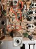
Photo attached.

thanks again for your help!

In AM signal strength 4 (80%)
R56-D13 -0.132v
R57-D18 -1.138v
R41-D10 -1.133v
 
Weak signals not received, and the detected voltage in FM looks rather low. I think it is probably a loss of gain in the 'front end'/IF strip.
Check the DC voltages on:
Qg1 Gate -
Source -
Drain -

Qg2 Base -
Emitter -
Collector -

Qg4 Base -
Emitter -
Collector -

Qg7 Base -
Emitter -
Collector -
 
Weak signals not received, and the detected voltage in FM looks rather low. I think it is probably a loss of gain in the 'front end'/IF strip.
Check the DC voltages on:

Qg1 Gate - B 0.03 Vdc
Source - C 0vdc
Drain - E 7.75 vac

Qg2 Base - 2.01vdc
Emitter - 1.4 Vdc
Collector - 12 Vdc

Qg4 Base - 1.9
Emitter - 1.175
Collector - 12.7

Qg7 Base - 2.86
Emitter - 0
Collector - 14
 
Back
Top Bottom