• The move to the new server is done. There are some software and database maintenance updates in process. This has us passing the hat around to help out. We appreciate any donations. Seriously, even a dollar helps. The payment page may be found here - https://www.audiokarma.org/support.html

Kenwood KR-5400 - Weak Output / Blowing transistor [ repair help]

QUiKSR20

AK Subscriber
Subscriber
Hey guys, hoping to figure out whats going on with this problematic KR-5400 I recently picked up.. As always I usually plug it in on the dimbulb
just to make sure it powers on ok and once the relay clicks and the bulb remains off ill unplug and start the cleaning process / audio testing etc.

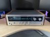
Before -

ext1.JPG

int1.JPG


After - ( Cleaned up great )

ext2.JPG

int2.JPG


Hope you guys dont mind the little story part above, I like to share some info before I just ask for help :)

So from here I gave it a test and this is where I started noticing some problems which ill get into..

One channel sounds ok / other sounds weak & distorted

Nothing crazy, I figure dirty controls like 90% of old gear we acquire.
  • Cleaned all controls pretty good ( can always go in again )
  • Cleaned the often forgotten switch on the back for 4ch mode & the protection relay contacts
Fire it back up and the same issue, One weak channel and one fine channel.. At this point I played it around 1/4 the way maybe a little louder just to see how it could sound
and I heard a POP and fizzle out.. Now the good channel is dead silent and the crappy channel is still there crappy.

This is where the troubleshooting begins
:
  • Search & Download the Schematic / Service Manual, ( GREAT There is no known service manual, Just a schematic ) X07-1350-10 Board Schematic - [ Click to view ]
  • Removed and tested all 4 output transistors ( All fine ) Cleaned / New Thermal Paste / Reinstalled
  • Removed and tested all 22 transistors ( 21 Good / 1 Bad on the channel that was playing fine ).
  • Checked the " Known Bad Transistor list " and searched for proper replacements.
Found 2 Known offenders that tested fine but should be replaced no matter what.
  • Replaced [ Q5 / Q6 ] 2SC1451B with KSC3503DSTU
Q20 appears to be the one that popped when I turned the volume up on the good channel
  • Replaced [ Q19 / Q20 ] 2SA743B with MJE253G - also did Q19 to match Q20
3 Bias Transistors were metal cans and looked funky / oxidized - tested fine
  • Replaced [ Q7 / Q8 / Q25 ] 2SC1416 with KSC1845 - 3 bias transistors

amp.JPG


Time to see if the repairs worked!
  • Power on ( no dimbulb issues )
  • Power on without dim bulb and play music ( both channels back but now both sound like the weak channel )
  • Checked Bias, Since theres no manual I went by this XRayTony Video which is the only technical info I can find.
They were way off assuming due to the new transistors I put in, They were at like 1mv.
  • Set both to 20mV
  • Checked DC Offset, Channel 1 is spot on for this unit around 14mV ( high but within range )
  • Checked DC Offset, Channel 2 is way off -76 offset ( no way to adjust on this unit )

Let it play music for a few which still sounds crappy and Pop no sound, Pull out the dim bulb and its LIT UP ( ugh ).
  • Remove Q20 - Part was VERY HOT
  • Power On ( dim bulb fine )
  • Check Q20 on the DCA55 ( SHORTED ON ALL 3 B/C/E )

So after all my babbling my questions are :

  1. What would you suggest checking next? The sound is the same but faint/weak on both channels ( Until Channel 2 popped a Q20 again )
  2. What could be causing Q20 to get so hot and die?
  3. What could be a reason for the DC Offset being so outta wack on that one channel.

This unit is pretty basic but with no service manual I can only do so much troubleshooting alone with my limited repair knowledge.

Thanks in advance guys!!!!
 
Last edited:
Register to hide this ad
Anyone have any ideas or things I could look into as next steps? Any help is greatly appreciated.
 
q18 q20 should be complimentary . and same in other channel . bd139 and bd140 might be fine there
maybe you installed q20 incorrectly. plus maybe whatever blew the original is still there . might be a failing output or a short in your speaker or wire .
 
A guess..
Before I start guessing, have you tested with headphones instead of speakers? Sometimes trouble with bad output will sound ok with headphones.
As to Q20 baking, My guess would be a problem with supply voltage to the output transistor. Sometimes the case connection (collector) gets loose, and no positive (or negative) supply to that output transistor. When this happens, the driver "sees" the load through the output B-E junction (will look like diode) and drive the load, exceeding its power rating. But don't over tighten the collector screws. See what voltages are on the collector (case) :dunno:
 
First thanks for the reply, As a new amateur tech ( but trying to learn the best I can ) the help you guys give is invaluable.

q18 q20 should be complimentary . and same in other channel .

Yeah Q18/Q20 in one channel are mirrored on the other channel as Q17/Q19 ( I believe ),

Q17 - Tested Fine and Reinstalled
Q19 - Tested Fine but Replaced with part MJE253G to match Q20
Q18 - Tested Fine and Reinstalled
Q20 - Failed & Replaced with the correct modern part MJE253G which failed again just like the original

bd139 and bd140 might be fine there

Not 100% sure what you mean here ( lack of knowledge on my part )


maybe you installed q20 incorrectly. plus maybe whatever blew the original is still there . might be a failing output or a short in your speaker or wire .

- Triple checked the installation on Q20 with my DCA55 and blew the original part as well

I think what blew the original part is still there and what im trying to figure out so I dont keep blowing transistors.

Speaker / Wire should be fine been using it with multiple stereos.

What I can tell you is the one channel that sounds weak still sounds weak and the channel that sounded good prior to blowing Q20 sounds weak now too when I replace Q20.

So both channels now sound the same ( Weak ) but one channel will blow Q20 again so I havent reinstalled it yet not wanting to ruin another transistor.

A guess..
Before I start guessing, have you tested with headphones instead of speakers? Sometimes trouble with bad output will sound ok with headphones.

I haven't but thats a great idea, Ill have to see if I have headphones that are not 3.5mm

As to Q20 baking, My guess would be a problem with supply voltage to the output transistor. Sometimes the case connection (collector) gets loose, and no positive (or negative) supply to that output transistor. When this happens, the driver "sees" the load through the output B-E junction (will look like diode) and drive the load, exceeding its power rating. But don't over tighten the collector screws. See what voltages are on the collector (case) :dunno:

This sounds like a good starting point, I did remove and reinstall them with new grease and snugged them good but not enough to strip them.
To test these would I just ground my black probe to chassis and touch the metal casing to see what readings I get?

When reinstalling I did make sure they were insulated and not shorting to the chassis...

Thanks guys!!
 
Last edited:
taking a guess here that there is a common connection to both channels of the negative supply to the output transistors and one side let go then the other side did the same later on either that or the drivers that blew it was one was stronger than the other .
p.s you can simply measure the voltages of the outputs cases with regard to speaker ground
 
qe24 may have lost its collector connection .. follow it back to the power supply .

Will do, This is probably one of the worst boards ive worked on in my short repair career, Traces lift up so easily.

taking a guess here that there is a common connection to both channels of the negative supply to the output transistors and one side let go then the other side did the same later on either that or the drivers that blew it was one was stronger than the other .
p.s you can simply measure the voltages of the outputs cases with regard to speaker ground

So you mean just connect to the negative speaker connection ( theres a nice post right on the board ) then just probe the output case ).. I follow... Standby ill test and see what I come up with.
 
I think your on to something @petehall347 , Check this out... With negative probe to negative speaker terminal I get the following readings to the output casings :

Q22 : 33.8v
Q24 : 0.0v
Q23 : -34v
Q21 : 33.8v

Another issue I found ( I checked this before but it could have changed ) im noticing is if I ground to the chassis and test continuity to the output transistor Q23
its beeping as if theres continuity to the chassis which I believe is bad news.( pulled the transistor its still good thankfully ).

Could this be a bad mica insulator or if there an issue where the screws go thru? This is not the sole issue but clearly is "A" Problem I need to fix.

So Q23 is beeping on the continuity test to the chassis ( Short ) and Q24 is showing 0v

So to summarize

The channel with Q24 is showing 0 volts when probing the Output and is toasting Q20
The channel with Q23 is showing the right volts but shows continuity to the chassis which is a short.

** Keep in mind if it matters , The transistor at Q20 is removed currently
 
Last edited:
q23 cant be shorted to ground and also have -34v on it . its most likely the main capacitor being in circuit

So provided Q23 is fine and its just an error on my part which is completely possible, Would the next step still be "Follow q24's collector back to the power supply and look for a break ." ?
 

Man you were spot on!!!!!!!!!!!!!!!

So I opened the bottom of the unit and set my meter to continuity mode.. For arguments sake I probed Q22's collector ( working output ) and touched various parts of the path ( Beeped at every one ).

Tried Q24 and and didnt even beep a few inches away, Removed all the solder and bent the metal tab ( not sure what to call it ) and then reflowed the solder. BOOM!!! Now it has continuity all over.

- Powered the unit on and set my meter back to volts and probed each Outputs Case

Q22 : 33.8v
Q24 : -34v
Q23 : -34v
Q21 : 33.8v

- Connected speakers

At this point one channel sounded perfect and one crappy/weak, So I powered it down and installed a fresh MJE253G at Q20.

Both channels are now working perfect and the transistors are nice and cool, Re-checked and set BIAS to 20mV.

@petehall347 I really appreciate the help!!! its fixed!! If you dont mind for my own knowledge would you mind explaining why you knew to check that collector or what led you too that? Just so I know for the future.

Gonna add some new bulbs now and give it a good long play and debate a re-cap in its future.

Thanks Again !!!
DG
 
it was actually @sregor that reminded me of a time it had happened to a unit i worked on some time ago .
what happens if an output loses its supply power the driver transistors try to do all the work and simply cant do and overheat and blow up .
https://audiokarma.org/forums/index...transistor-repair-help.1001251/#post-15744044

Well @sregor my apologies for not including you above, Thanks a ton!!! This unit is now making sweet music and I learned some more tips/tricks for my next receiver I tackle.. Each one I get my
hands on I learn more thanks to you you guys.. I just love refurbishing them and putting them back in the wild for someone to enjoy for years to come. I build / gift entry level vintage systems to people in a small vinyl community I belong too.
 
Put around 24 hours on this unit with zero issues, Now that I consider it fixed I gave it some new bulbs ( all the old ones were dead ).

IMG_6326.JPG

Thanks again guys, Without your help none of this is possible.
 
Greetings all!

Noob here and apparently following in QUIKSR20's footsteps. I've had formal electrical training (4 year apprenticeship) in the distant past (70s), but our instruction just touched on electronics. It was more about commercial/industrial wiring, conduit bending, etc.

Anyway I'm now retired and have lots of time to work on hobbies. I pulled out the Kenwood KR-5400 I've had since the late 70s from under a bench in my workshop and fired it up. It worked kinda, but then I noticed one channel dropping out. I too found the xraytonyb video about the KR-5400 and my education began. I pulled the covers off and cleaned all the moving knobs etc with contact cleaner then deoxit. It seemed to work better then started dropping a channel again. What's weird is the dropped channel could be left or right or both.

So thanks to xraytonyb I started digging. First thing I found was that the bias voltage on the left set of resistors (big green ones) was -20 and the right set was about +18 mv. I tweaked the right one up to 20, but the left set would only adjust to -0.7 with that pot turned all the way.

Next I found that the DC offset was +20 ish on pin 10 to ground and 0 on pin 9 to ground (pins adjacent to protect relay).

So knowing very little, I just started doing what xraytonyb did. I installed new 6800uf capacitors. That did nothing. I now have all 4 power transistors out (Qe19,21 and Qe20,22) and waiting on silicon paste. Btw the old transistors checked out ok, so I'm not too optimistic that the new ones are gonna fix anything.

This is all very new/challenging for me and I would really appreciate you guys/gals help as I proceed.
For clarification purposes:
Channel 1 is left, 2 is right?
Odd number transistors on schematic are left channel, even number are right channel?
When looking at main amp from the front, the left set of resistors where you measure bias goes to left channel, right set go to right channel?
The even/odd numbering thing does not apply on all parts on the schematic correct? Example: pin #9 by the protect relay goes to right channel.

I am doing all this through a dim bulb tester that I rigged up, so hopefully I won't fry anything/create new problems!
 
Welcome to AK!
Number one cause of channels cutting out is relay contacts. A simple test is to tap relay with something non-metallic and see if the channels cut out. They can be taken apart, and cleaned and check the spacing - sometimes it is just a matter of burnishing contacts and closing the gap alittle, but most techs replace it. YMMV.
other possibilities are controls or switches (filter switches maybe). No pre-main connections to look for on this model. Good luck with it.
 
Back
Top Bottom