• The move to the new server is done. There are some software and database maintenance updates in process. This has us passing the hat around to help out. We appreciate any donations. Seriously, even a dollar helps. The payment page may be found here - https://www.audiokarma.org/support.html

Kenwood KR-8050 FM No Sound

Brivan

Well-Known Member
Hello, all

I have a Kenwood KR-8050 that has (most of the time) no sound when using FM. If the receiver sits overnight, the next day, I get FM stereo from a strong local station for a minute or two, then then audio quickly dwindles to nothing. When it's working, the audio is somewhat distorted and it gets even more distorted as it's fading out. The stereo light goes out at the same time, but the tuning and signal strength meters indicate a strong station as they did before. AM works fine, as well as auxiliary input (I haven't tested phono input, yet).

I measured voltages of ICs 1 through 6 and have the results listed below. I'm not a genius at tuners, so I'm looking for a little help with isolating the cause. My guess it's with the furthest component upstream that shows measurements contrary to what the schematic gives - in this case IC2.

Expected values from the schematic are listed first; measured values second.

IC1
1: 1.3; 1.3
2: 1.3; 1.3
3: 0; 0
4: 11.4; 13.2
5: 12; 14.2
6: 11; 1.3
7: 11; 12.5
8: 12; 13.8

IC2
1: 2; 2.1
2: 2; 2.1
3: 2; 2.1
4: 0; 0
5: 0; 0
6: 5.6; 6.1
7: 5.6; 6.5
8: 5.6; 5.7
9: 5.6; 5.7
10: 5.6; 5.7
11: 13; 15
12: 5.2; 5.2
13: 0.7; 5 tuned; 2.6 detuned (problem here?)
14: 2.2; 0 (problem here?)
15: 0; 0.6 tuned; 4.8 detuned (problem here?)
16: 0; 3.8 (problem here?)

IC3
1: 0; 0
2: -0.5; -0.7
3: -0.5; -0.7
4: 0; 0
5: -11; -12.5
6: 12.5; 13.2
7: 0; 0
8: 5.5; 5.7
9: 0; 0
10: 5.5; 5.7
11: 0; 0
12: 13; -12.5 (schematic typo?)
13: 0; 13.2 (schematic typo?)
14: -13; 0 (schematic typo?)

IC4
1: 0; 0
2: 0; 0
3: 0; 0
4: 2; 2.2
5: 6.2; 7.2
6: 2; 2.3
7: 2.8; 3
8: 7.8; 14.4 (problem here?)
9: 5; 3.1
10: 4; 5.1
11: 8; 9
12: 13; 14.4
13: 4.2; 4.5
14: 0; 0
15: 0; 0
16: 0; 0

IC5
1: 13; 14.7
2: 3; 3.5
3: 5; 4.9
4:0.6; 0.7
5: 10; 11.7
6: 10; 11.7
7: 0; 0
8: 0; 14.5 (switching to mono brings this value closer to 0)
9: 5; 5.7
10: 2.6; 2.7
11: 2.6; 2.7
12: 2.6; 2.7
13: 2.6; 2.7
14: 2.6; 2.7
15: 2.6; 4.2
16: 3; 2.9

IC6
1: 0; 0
2: 0; 0
3: 0; 0
4: -11; -12.3
5: 0; 0
6: 0; 0
7: 0; 0
8: 11; 12.4

Thank you!
 
Register to hide this ad
This morning, I got FM audio briefly after power-up. Of the noted voltage variations in the previous post, IC4-TR4010 pin 8 was the only one that measured differently with the FM audio working. It was now at 10.9v. I held the meter probe on it until the audio fizzled out (about a minute) and, as the sound went away, the voltage increased to yesterday's reading of 14.4v. Also, I was able to trace FM audio to the input-side of L8, but it ended there. Out of curiosity, I briefly jumpered L8, but got only quiet FM static through the receiver's speakers, which I thought was odd, since my signal tracer was clearly picking up FM audio. I also replaced C35 and C36 to no avail.

Finally, I jumpered the FM audio signal from pin 8 of IC2-HA11225 (audio out) to pin 4 of IC4-TR4010 (audio in) and got nothing from the receiver's speakers. When I moved my jumper from pin 4 of IC4 (audio in) to pin 5 of IC4 (audio out), I got audio out through the speakers. So, it appears that IC4-TR4010 isn't working. There don't appear to be any datasheets available for the Kenwood-specific TR4010, so I can't surmise the problem any further than this. That particular IC isn't available, so I have a replacement tuner board ordered from Ebay. I'd like to pull the TR4010 from the working replacement board and replace it in an effort to learn something but, since that IC is rare, I don't want to risk damaging it by desoldering it, so my plan is to replace the entire board. I'll update this thread with my results.
 
That's unfortunate. Finding a "TR4010A" is like looking for nipples on a fish. I suspect that it is a re-badged CD4010 and is used as a PLL-style lock, but I could be way off-base here.
 
I jumpered the FM audio signal from pin 8 of IC2-HA11225 (audio out)
Pin 8 isn't audio out. They are tapping the signal at the output of the final FM IF amp, so the signal at pin 8 is still 10.7 MHz.
IC3 does a frequency shift of that 10.7 MHz signal to get it in a range that IC4 can process. So it could be IC3.

It looks like all the components are there, so you might find composite audio out of IC2 pin 6.
 
Pin 8 isn't audio out. They are tapping the signal at the output of the final FM IF amp, so the signal at pin 8 is still 10.7 MHz.
IC3 does a frequency shift of that 10.7 MHz signal to get it in a range that IC4 can process. So it could be IC3.

It looks like all the components are there, so you might find composite audio out of IC2 pin 6.
From the attached schematic, it was my assumption that the signal path followed the bold line through the FM IF and AF sections. I can check, again, but I'm fairly certain I was getting audio out of IC2 pin 8. I also had audio at IC3, pin 10, IC3, pin6 and at the input to L8. That's where it stopped, however. It was my assumption that IC4 was the cause of it - mostly since I was seeing goofy voltage readings on IC4, pin 8. One thing I haven't done is pull IC4 from the circuit. I'd be interested to see if my audio signal would then at least make it to the pin 4 position with the IC removed.
 

Attachments

Last edited:
That's unfortunate. Finding a "TR4010A" is like looking for nipples on a fish. I suspect that it is a re-badged CD4010 and is used as a PLL-style lock, but I could be way off-base here.
I looked at schematics for a few CD4010 IC's and it doesn't appear to be the same as a TR4010 - based on Vcc and ground points, to name a few. The description for a CD4010 is "non-inverting hex buffer" so I don't even know for sure if I'm looking at the right part.
 
Last edited:
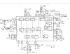
Annotation 2020-03-13 094729.png
Above is the 'IF System' chip, IC2. Output at pin 8 is from the 3rd IF amp.
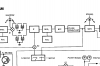
Annotation 2020-03-13 095244.png
Here is the signal flow per the SM. Signal from output of IF is at 10.7 MHz, and passes into Mix2 where it is converted to 10.7MHz * (9/49) = 1.965 MHz.
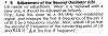
Annotation 2020-03-13 100929.png
From Mix2 it passes through some filtering and goes to the pulse counter FM demod. A 'pulse counting FM demod' is really not much more than a digital one-shot that converts a variable frequency input to a variable duty cycle digital pulse output.

I really think a scope will be needed to systematically troubleshoot this one. Or 'shot gun' by replacing random parts.
 
View attachment 1792093
Above is the 'IF System' chip, IC2. Output at pin 8 is from the 3rd IF amp.
View attachment 1792105
Here is the signal flow per the SM. Signal from output of IF is at 10.7 MHz, and passes into Mix2 where it is converted to 10.7MHz * (9/49) = 1.965 MHz.
View attachment 1792108
From Mix2 it passes through some filtering and goes to the pulse counter FM demod. A 'pulse counting FM demod' is really not much more than a digital one-shot that converts a variable frequency input to a variable duty cycle digital pulse output.

I really think a scope will be needed to systematically troubleshoot this one. Or 'shot gun' by replacing random parts.
I've got a scope. You were very helpful in getting my Realistic STA-860 (and STA-790) to receive FM in stereo - link here: https://audiokarma.org/forums/index...uned-and-stereo-leds-not-illuminating.901098/
I'd be more than happy to do some troubleshooting with the scope. Let me know what you'd like me to measure. Thanks!
 
Got some errands to run this afternoon, but you could start by tuning to a strong FM station and putting the scope on IC2 pin 8. You should see a signal at 10.7 MHz. It may be difficult to get a good sync on it due to the FM modulation, but you should be able to identify magnitude and approximate frequency. Should be more stable during quite periods in the audio. Then follow the signal path and be sure that 10.7 MHz signal is also at IC3 pin 10. I'll need to look at the IC3 (MC1496P) datasheet a bit before going further.
 
I have a three hour commute every day (round trip). I usually listen to a thumb drive in the dash or my smart phone through blue tooth - stuff like youtube and pod-casts. A few days ago I got into the car and didn't have my phone. I turned on the FM radio and suddenly realized I had not used it in years. I then realized that other than when I hooked it up to make sure everything was working, I have not used the tuner in my Mitsubishi "pre-amp tuner" in my main listening room since then.

Frankly, Streaming has completely displaced FM for me. I like having it around, but I never actually use it.
 
Got some errands to run this afternoon, but you could start by tuning to a strong FM station and putting the scope on IC2 pin 8. You should see a signal at 10.7 MHz. It may be difficult to get a good sync on it due to the FM modulation, but you should be able to identify magnitude and approximate frequency. Should be more stable during quite periods in the audio. Then follow the signal path and be sure that 10.7 MHz signal is also at IC3 pin 10. I'll need to look at the IC3 (MC1496P) datasheet a bit before going further.
That works for me - I'm trying to button up a Pioneer QX-949 this afternoon, but it's giving me some unexpected static in one channel, so I'll probably spend the rest of the day hunting that down. I'll likely get back to the KR-8050 on Monday. Have a good weekend and thank you!
 
Got some errands to run this afternoon, but you could start by tuning to a strong FM station and putting the scope on IC2 pin 8. You should see a signal at 10.7 MHz. It may be difficult to get a good sync on it due to the FM modulation, but you should be able to identify magnitude and approximate frequency. Should be more stable during quite periods in the audio. Then follow the signal path and be sure that 10.7 MHz signal is also at IC3 pin 10. I'll need to look at the IC3 (MC1496P) datasheet a bit before going further.
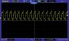
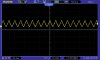
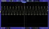
Okay, we're back at it. With the receiver tuned to a strong FM station, here's what I have on IC2, pin 8:
IC2 Pin 8.jpg

And here's what I have on IC3, pin 10:
IC3 Pin 10.jpg
 
The signal on IC2 pin 8 looked a little goofy, so here's IC2 pin 1. It's a little more like what I'd expect:
IC2 Pin 1.jpg
 
Got some errands to run this afternoon, but you could start by tuning to a strong FM station and putting the scope on IC2 pin 8. You should see a signal at 10.7 MHz. It may be difficult to get a good sync on it due to the FM modulation, but you should be able to identify magnitude and approximate frequency. Should be more stable during quite periods in the audio. Then follow the signal path and be sure that 10.7 MHz signal is also at IC3 pin 10. I'll need to look at the IC3 (MC1496P) datasheet a bit before going further.
Tomorrow (3/18), I'm planning on replacing the tuner board with a donor purchased from Ebay. Considering the state of the world, right now, I certainly don't expect immediate help on this, so I'm going to trudge ahead. If, for some reason, the replacement board doesn't work out, I might end up putting the original back in and returning to this thread - hopefully society will be a little less fraught with disaster, then. Thanks, again, for all you help!
 
Actually, this is a reasonably good time to catch up on repairs. As long as parts deliveries are not interrupted, and newly acquired gear is isolated sufficiently so that any transmission concerns are resolved, the bench is a pretty good place to be.
 
Actually, this is a reasonably good time to catch up on repairs. As long as parts deliveries are not interrupted, and newly acquired gear is isolated sufficiently so that any transmission concerns are resolved, the bench is a pretty good place to be.
Yes, definitely! Also, I got the replacement tuner board installed and it works fine. I ran into a little trouble getting the tuning meter to center, since a small part of the slug broke off inside the inductor when I tried to turn it. No problem, I thought - I've got a spare board! I had the same thing happen when I removed the slug from that inductor, too - fortunately it was a smaller piece and I was able to get the tuning meter centered using the less-broken replacement slug (barely). This isn't the first time I've had a tuning slug break apart when trying to move it, so I'm wondering if using a penetrating fluid of some kind (DeOxit Fader Lube, maybe?) on the inductor slug would be a good idea in order to reduce the likelihood of the slug breaking when trying to turn it. BTW the breakage is usually in the middle of the slug or, like what happened to me recently, on the bottom tip of it.
 
Back
Top Bottom