• Please note that Audiokarma will be offline briefly for updates early on Monday morning, September 28th.

Kenwood KR-9050, need help with diagnosis (Help me Save this Amp)

grafxdesin

AK Subscriber
Subscriber
I have a Kenwood KR-9050 that I am trying to fix. It has lots of issues but so far the pre-amp is working, but I am having issues in the power amp. Ill explain what I am seeing and give my transistor readings below. Hopefully this info can help you point me in the right direction to look.
1. I have removed the X07-1690 board, this is the whole heatsink with outputs
2. When this is removed, I can get the speaker relays to click and my DBT goes down enough for them to click
3. With this board in circuit, my DBT goes sort of dim, but no relay click, feels unsafe.
4. The right channel (Even numbers) is a complete mess with burnt resistors and shorted transistors
5. The left channel (odd numbers) looks good and I am trying to get it stable so I can then work on the right channel, this is where I need help.
6. Why is my DBT not going out with the X07-1690 connected?
7. On the X07-1690, I have tested all the transistors and diodes with my DCA55, all test good.

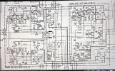
My transistor readings below with 3 of them having wrong readings, I also attached the schematics for the area I am working on in hopes someone can point me in the right direction.
Q3, Q5, Q7, Q15, Q16, Q17, Q18, Q19, Q20, Q21, and Q22 all tested correct or very close, I can and will post if needed.

Q9 B 74v
C .2mv (Should be 1.1V)
E 72V
Q11 B 71V
C 72.4v (Should be 5.0V or 50V, hard to read)
E 72V
Q13 B -73V
C -73V (Should be -1.1v)
E -74V

Any help is greatly appreciated, if you need something else, just ask.
 

Attachments

  • IMG_6322.jpeg
    IMG_6322.jpeg
    168.7 KB · Views: 7
Register to hide this ad
You might consider posting this in the Kenwood/Trio forum. Lots of Kenwood gurus there.
 
Q9 B 74v
C .2mv (Should be 1.1V)
E 72V
Q11 B 71V
C 72.4v (Should be 5.0V or 50V, hard to read)
E 72V
Q13 B -73V
C -73V (Should be -1.1v)
E -74V

These 2 don't "add up"
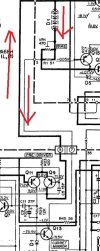
Q9c should "set" Q13c via path through D1 and R1
Measure Vdc one side of D1, repeat for other side, maybe Q13 failed c-e short or is in saturation.

Wait for the kenwood gurus...
 
These 2 don't "add up"
Q9c should "set" Q13c via path through D1 and R1
Measure Vdc one side of D1, repeat for other side, maybe Q13 failed c-e short or is in saturation.

Wait for the kenwood gurus...
I will check in the morning. I will check D1 on both sides, but do you mean R1? R1 is 1K and is way up stream if I am reading the schematics right.
When you say "saturation", what does that mean?
 
I will check D1 on both sides, but do you mean R1? R1 is 1K and is way up stream if I am reading the schematics right.
I'm looking at the path from Q9c to Q13c, see red arrows below. Note that D1 and R1 are in this path

When you say "saturation", what does that mean?
Google "transistor saturation"

Transistor is operating as a switch rather than in the linear region.
Means emitter and collector are at about the same voltage (see Vce sat in datasheet)

This was an error on my part, Q13e will not set Q13c so ignore the saturation comment.
 

Attachments

  • KR5.jpg
    KR5.jpg
    63.7 KB · Views: 3
I'm looking at the path from Q9c to Q13c, see red arrows below. Note that D1 and R1 are in this path
I was thinking you meant D1 and R1 on X07-1680, not 1690. These measurements are without the X07-1690 in circuit or connected.
 
These measurements are without the X07-1690 in circuit or connected.
Yep, my bad, can't blame Q13c in this case, it's just floating...

Next candidate would be Q11c, I would be leaning towards 5V, note that it's the same transistor as Q9 and seeing roughly the same input voltages albeit Q9c is not connected.

Think you are going to need all voltages for that front end Q3,5,7 b/c/e and fet Q1 G/S/D voltages. I've read a few posts where the fet was suspect and people reflowed the solder connections and all was good, yeah I'm a little sceptical but it only takes a few minutes.

3. With this board in circuit, my DBT goes sort of dim, but no relay click, feels unsafe.
Probably better to troubleshoot with this board in place. If you used a 75-100W bulb would it be safe to troubleshoot?
 
Thanks, I am on a work trip for the next couple days. I did measure Q1 a few days ago and got the correct reading, but I will measure again when I am home.
1. Should I take measurements again with X07-1690 in circuit?
2. My original reasoning for having it disconnected was to work one section at a time and make it stable.
 
Happy that you work on one channel at a time so ok to disconnect the other.
With X07-1690 connected is the DBT stable with a 75-100W bulb, does it look "safe"/no overheating...
This is the preferred configuration. If not safe then troubleshoot without X07-1690
 
Alright, finally got the weekend to tackle this amp. Hopefully we can figure it out together.
Here is where we stand:
1. With X07-1690 not collected, I can get the speaker relays to click. but I am getting the strange readings that I posted in the first post. Nothing has changed
2. With X07-1690 connected, My DBT goes down but not all the way. I would say it's a 2 out of 10 in brightness. I get no relay click even if I wait a minute. It is a 100 watt bulb. I do not believe it's safe to turn this amp on without my DBT.
3.Q11, the collector is showing a much higher voltage, I did test this transistor with my DCA55 and it tested ok, Could it be bad? If so, what is a replacement? On a side note, my DCA55 has always been correct so far for me.
4. Reading for Q3, 5, 7 etc are below:

Q3 E -69v
C .68v
B -68V

Q5 E 20V
C 72v
B 20.7V

Q7 E 20V
C 74V
B 20V

Q1 (I don't know how to read this type of transistor, so I went from left to right
1. 20.2V
2. 40mv
3. .76v
4. Not soldered, looks like this is how i came,
5. .75v
6. -.3mv
7. 20.8v

I am around most of this weekend so hopefully together we can get one channel stable. Ill check this thread throughout the day. Let me know what you think is wrong or what else I could check. Appreciate all your help so far
 
  • Like
Reactions: mbz
2. With X07-1690 connected, My DBT goes down but not all the way. I would say it's a 2 out of 10 in brightness. I get no relay click even if I wait a minute. It is a 100 watt bulb. I do not believe it's safe to turn this amp on without my DBT.
Continue testing with X07-1690 connected and with DBT unless others request differently

4. Reading for Q3, 5, 7 etc are below:
These voltages look good, in future please go to 1 decimal place to confirm Vbe is ok

3.Q11, the collector is showing a much higher voltage,
As above, front end voltages look good, so need to move deeper.
Previously it was Q9c that was high though 1690 board not connected.

Please post Q9, Q11 b/c/e voltages.
Please repeat Q5, Q7 b/c/e voltages to 1 decimal place.
Guessing Q5 is on and Q7 is borderline off.
 
@mbz, sorry this took me a little longer than expected but I am not giving up. This is mostly a weekend thing for me. See below:
With X07 1690 connected on my DBT with it still slightly lit, 2 out of 10, I got the following readings.

Q3 E -35v (Starts at -36v and slowly drains to -34v and a little lower)
C .6v
B -36.5v

Q5 E 20.1V
C 39.7v
B 19.5v

Q7 E 20.1v
C 39.7v
B 19.5v

Q9 E 40.5
C 1.1v (Seems to be correct)
B 39.7

Q11 E 40.6
C 22.2v (This seems to be the issue)
B 39.8v

Q13 E -40.8
C -1.3
B -40.1

Q1
D1. 20.1v
G1. -.0033v
S1. .7v
NG
S2. .7v
G2. -.004v
D2. 20.1v

These reading tell me Q11 might be the issue, does that sound right? If so, what is a good replacement for Q11?
 
  • Like
Reactions: mbz
Generally voltages look good, Q11c as you've pointed out looks suspect, its partner Q9 is seeing the same B, E voltages but giving a different Vc. Suggest replace Q11 and Q9 as a matched pair. Sm has Q11 as 2SB718(B or C rank)

2SB718 bce 200V 50mA 1.25W hfe=60-200 140MHz, 5.5pf
I'm poor on transistor matching, others better, looks like a driver transistor

Q5 E 20.1V
C 39.7v
B 19.5v

Q7 E 20.1v
C 39.7v
B 19.5v
Probable typo/misidentified B,E legs, expect Vb > Ve
 
2SB718 bce 200V 50mA 1.25W hfe=60-200 140MHz, 5.5pf
Try
TTA004B ecb 160V 1.5A 1.5W hfe=80-? 100MHz 17pf
Note different pinout, need to rotate 180degrees
A bit of overkill with Ic=1.5A, would have liked lower capacitance
 
Thank you, I have 2 TTA004B on hand so I can try them out in the morning. I will report back and get updated readings as well.
 
Back
Top Bottom