• The move to the new server is done. There are some software and database maintenance updates in process. This has us passing the hat around to help out. We appreciate any donations. Seriously, even a dollar helps. The payment page may be found here - https://www.audiokarma.org/support.html

Kenwood KR-9400 amp board modifications

Jmayfield23

New Member
Hello everyone, I’m new to the whole stereo and receiver world, but have been involved in electronic repairs for around 10 years. A friend of mine asked me to try to find out what’s wrong with his Kenwood KR-9400. Being 27, I’m, not too familiar with the old age electronics, and definitely don’t want to mess anything up.

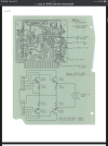
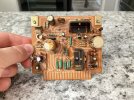
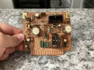
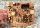
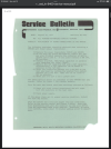
Anyways, the problem with his 9400, is whenever he turns it on, the relay doesn’t activate, and there is no output. He also mentioned that started to hum before the sound went out completely. The LED for FM stereo doesn’t light up, and same with the meter lights in the front, and the tuning peg light, if it has one, I’m not sure. I took a look at some photos online, looked through forums, found the manual, and eventually I was comfortable to open this thing up. I opened it up, and of course its from a smokers home, so things are brown and sticky. Yay. Besides that, things look decent inside. It has been worked on previously by other shop when it was owned by someone else. I removed the amp boards (X07-1390-10 x2) and inspected for any damages. The beginning of the manual shows a Service Bulletin about replacing all output transistors, and the amp boards I pulled out have a part attached to the back of them as if the repair was started, but not finished.

Can anyone help me out with this?
 

Attachments

  • IMG_0013.png
    IMG_0013.png
    432.7 KB · Views: 40
  • IMG_0014.png
    IMG_0014.png
    456.7 KB · Views: 41
  • IMG_0009.jpeg
    IMG_0009.jpeg
    152.6 KB · Views: 41
  • IMG_0010.jpeg
    IMG_0010.jpeg
    141.3 KB · Views: 37
  • IMG_0011.jpeg
    IMG_0011.jpeg
    157.6 KB · Views: 38
  • IMG_0012.jpeg
    IMG_0012.jpeg
    149.4 KB · Views: 39
Register to hide this ad
The first thing you need to do is build a Dim Bulb Tester -- it's simple, just an incandescent light bulb ( NOT an LED) in series with the hot side of the plug. Specs on the site, do a search.

This acts as a current limiter so that you won't blow anything up =due to excess current flow. Should flash bright as the main caps charge, then dim down quite a bit. Final brightenss is determined by bulb wattage and idle current draw on the equpiment but should be pretty dim. Likely in your case it will stay brighter than it should, indicating a short.

On the first amp board pic it looks like on of the large caps has vented. The smaller ones have already been replaced, but any factory caps in a 50 year old receiver are suspect at best.

For troubleshooting, typical amp failures are shorted output transistors (check them using the six way diode test), power supply issues, and other failed components.

I'd start with checking for shorts to ground on the output transistors and shorts between the legs (not familiar with that receiver, I think it has the old type transistors on the heat sink, not modern three-legged ones. Case will be collector if they are. Then I would check the voltage on the output, you will have to find a spot before the relay since it's not closing. With no input and the volume all the way down, voltage must be less than 100mV or so. May be able to adjust on this amp. Likely it's off.

Note that Kenwoods of that era are known for cracked solder joints, a close inspection is in order.

Check voltage on power rails, must be close to factory spec and the same on both positive and negative rails.
 
Last edited:
It's hard to tell but are the resistors above the large cap on both boards just dark colored or cooked?


Screenshot (364).jpg
 
The first thing you need to do is build a Dim Bulb Tester -- it's simple, just an incandescent light bulb ( NOT an LED) in series with the hot side of the plug. Specs on the site, do a search.

This acts as a current limiter so that you won't blow anything up =due to excess current flow. Should flash bright as the main caps charge, then dim down quite a bit. Final brightenss is determined by bulb wattage and idle current draw on the equpiment but should be pretty dim. Likely in your case it will stay brighter than it should, indicating a short.

On the first amp board pic it looks like on of the large caps has vented. The smaller ones have already been replaced, but any factory caps in a 50 year old receiver are suspect at best.

For troubleshooting, typical amp failures are shorted output transistors (check them using the six way diode test), power supply issues, and other failed components.

I'd start with checking for shorts to ground on the output transistors and shorts between the legs (not familiar with that receiver, I think it has the old type transistors on the heat sink, not modern three-legged ones. Case will be collector if they are. Then I would check the voltage on the output, you will have to find a spot before the relay since it's not closing. With no input and the volume all the way down, voltage must be less than 100mV or so. May be able to adjust on this amp. Likely it's off.

Note that Kenwoods of that era are known for cracked solder joints, a close inspection is in order.

Check voltage on power rails, must be close to factory spec and the same on both positive and negative rails.
Just left Lowe’s with the items needed for a tester, forgot to mention that on my original post saying that was on the to do list for today.

I’ll check on everything, but with the relay, with the amp boards out, the relay does work.
 
It may also be glue. Some of this glue is corrosive so check all components that have glue attached.
Seems to be glue. Same with other amp board that looks like it may have popped, I think it’s just the glue from the factory on top of the cap and resistors. Also, found 1 bad transistor on one of the amp boards doing the 6 way diode test. @HPMguy
 
So after plugging it into the dim bulb tester, I don’t get any kind of light when plugging it in without the amp boards, but the relay will actuate. When I have 1 board placed on the right side, the bulb turns on, then dims as it should, but the relay won’t actuate. When a board is placed alone on the left side, bulb stays lit, dead short, even with a 300 W bulb (primarily using a 100W bulb, was just curious). Looks like I need to probably swap out the caps and transistors on the amp boards, and find the short on the left side of the power supply where the amp boards goes into that connector.

Any other ideas?
 
So after plugging it into the dim bulb tester, I don’t get any kind of light when plugging it in without the amp boards, but the relay will actuate. When I have 1 board placed on the right side, the bulb turns on, then dims as it should, but the relay won’t actuate. When a board is placed alone on the left side, bulb stays lit, dead short, even with a 300 W bulb (primarily using a 100W bulb, was just curious). Looks like I need to probably swap out the caps and transistors on the amp boards, and find the short on the left side of the power supply where the amp boards goes into that connector.

Any other ideas?
The first thing you need to do is build a Dim Bulb Tester -- it's simple, just an incandescent light bulb ( NOT an LED) in series with the hot side of the plug. Specs on the site, do a search.

This acts as a current limiter so that you won't blow anything up =due to excess current flow. Should flash bright as the main caps charge, then dim down quite a bit. Final brightenss is determined by bulb wattage and idle current draw on the equpiment but should be pretty dim. Likely in your case it will stay brighter than it should, indicating a short.

On the first amp board pic it looks like on of the large caps has vented. The smaller ones have already been replaced, but any factory caps in a 50 year old receiver are suspect at best.

For troubleshooting, typical amp failures are shorted output transistors (check them using the six way diode test), power supply issues, and other failed components.

I'd start with checking for shorts to ground on the output transistors and shorts between the legs (not familiar with that receiver, I think it has the old type transistors on the heat sink, not modern three-legged ones. Case will be collector if they are. Then I would check the voltage on the output, you will have to find a spot before the relay since it's not closing. With no input and the volume all the way down, voltage must be less than 100mV or so. May be able to adjust on this amp. Likely it's off.

Note that Kenwoods of that era are known for cracked solder joints, a close inspection is in order.

Check voltage on power rails, must be close to factory spec and the same on both positive and negative rails.
Was also going to ask if I test the voltage with the amp boards in or out?
 
So after some more checks, the short goes away when removing the connectors on the left and right side of the power supply board, taking out the left side heat sink and all of those boards. The lightbulb stays dim, doesn’t get bright, but just stays dim. No relay click
 
Last edited:
Just a thought—you said someone else maybe worked on this unit already? Maybe started the service bulletin mods?

Are the transistors at Qe4 the original 2SD381 or have they been replaced by something else by any chance? I can’t quite tell from your picture but they look like they might be new parts.

I found out from my own experience restoring my KR-9400 that it is VERY picky what goes at Qe4 and can go wildly unstable if it doesn’t like it. Caused my to pull my hair out for a good long while.

If those are original and working…just carry on, then…

I was really impressed by the KR-9400 once it was finished.
 
Back
Top Bottom