YANIR GVIRTz
New Member
Recently purchased a working KR8050 and decided to recap following the great post of Super Noob (https://audiokarma.org/forums/index.php?threads/project-kenwood-kr-8050.882572/).
Unit is in generally good condition, with no evidence of prior work on PCB's or anywhere else .
However; on the Pre-Amp (X08-1740-10A/G) section I noticed 2 strange things:
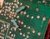
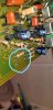
1. Two resistors on back side seem non-original work (They were connected to 2 capacitors that I removed, and the whole area seems like it has been worked on - a little sloppy job).

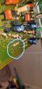
2. Two resistors (R32 and R34) on top have been clipped away.
I can solder, but definitely don't have the electronic background to figure out what is going on here.
Would highly appreciate if anyone could help me read these tea leaves...
1. Any idea why would someone do this?
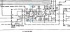
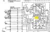
2. Should I re-install original resistors? Service manual has R32 at 62K and R34 at 100K.
3. Should I remove the green resistors on back?
Please see images attached.
BTW - Super Noob pictures clearly shows R32 and R34 in place on his Pre Amp board.
Thank you!
Unit is in generally good condition, with no evidence of prior work on PCB's or anywhere else .
However; on the Pre-Amp (X08-1740-10A/G) section I noticed 2 strange things:
1. Two resistors on back side seem non-original work (They were connected to 2 capacitors that I removed, and the whole area seems like it has been worked on - a little sloppy job).
2. Two resistors (R32 and R34) on top have been clipped away.
I can solder, but definitely don't have the electronic background to figure out what is going on here.
Would highly appreciate if anyone could help me read these tea leaves...
1. Any idea why would someone do this?
2. Should I re-install original resistors? Service manual has R32 at 62K and R34 at 100K.
3. Should I remove the green resistors on back?
Please see images attached.
BTW - Super Noob pictures clearly shows R32 and R34 in place on his Pre Amp board.
Thank you!