It's been a very long time since I did any repair projects, but I've had some time on my hands lately and got inspired to spend some of my hobby time on this again. Starting with a KLH Model 20.
The nicest-looking one was totally dead when I found it, it'd power on and draw some power, but no output or response anywhere. I replaced the electrolytic capacitors and cleaned the controls, adjusted the bias per service manual, cleaned the function switch, and now got a test signal through the unit but with a bad channel imbalance when hooked up to a dummy load.. The volume control ended up having cracked leads at the board, so I replaced it with a donor (I have a few parts units I got at the same time) and checked the other controls which looked good but they got fresh solder for good measure.
Now, with the unit connected to a test signal (1 kHz tone) going into the Aux input, and the amp connected to a dummy load, the channels are beautifully matched and show perfect sine waves on the scope. But if I hook it up to my speakers...it's bad. Wild siren noises at maximum volume until I quickly power the unit off. I torqued down the chassis bolts which hold the halves together, and this didn't change anything.
Okay, not great, but I figured it might be a grounding issue - with the unit on an isolation transformer, and an isolation transformer on the audio signal, I get a moderately loud feed-through tone even at zero volume from the left channel, and never manage to get any sound out of the right channel at all. There's a lot of noise as well.
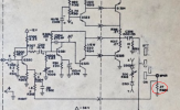
Voltages look pretty close, -36V was a -39V but the others were within 10% (edit: 39 vs3 6 is....also within 10%. Math.) Wire routing is all original. This is a later production one, it looks like, the power amp board has 1 fewer capacitor populated and it has silicon output transistors. It also has an MX-3 (or maybe the MX-6) MPX board, although the power supply has a 4th capacitor populated which is labeled in the manual "not provided with MX-3 board" so I'm not positive, but I already know KLH has played mix-and-match on different production revisions without great documentation from past experience years ago.
I used to consider myself an advanced tech (although not quite an expert) but it's been long enough of not doing it or thinking about it that loads of the knowledge has been paged out. I'd love some guidance and suggestions for where to go next. I have detailed photos of the work and some scope waveforms saved I can share if that's helpful at this stage. I appreciate anyone's input here!
The nicest-looking one was totally dead when I found it, it'd power on and draw some power, but no output or response anywhere. I replaced the electrolytic capacitors and cleaned the controls, adjusted the bias per service manual, cleaned the function switch, and now got a test signal through the unit but with a bad channel imbalance when hooked up to a dummy load.. The volume control ended up having cracked leads at the board, so I replaced it with a donor (I have a few parts units I got at the same time) and checked the other controls which looked good but they got fresh solder for good measure.
Now, with the unit connected to a test signal (1 kHz tone) going into the Aux input, and the amp connected to a dummy load, the channels are beautifully matched and show perfect sine waves on the scope. But if I hook it up to my speakers...it's bad. Wild siren noises at maximum volume until I quickly power the unit off. I torqued down the chassis bolts which hold the halves together, and this didn't change anything.
Okay, not great, but I figured it might be a grounding issue - with the unit on an isolation transformer, and an isolation transformer on the audio signal, I get a moderately loud feed-through tone even at zero volume from the left channel, and never manage to get any sound out of the right channel at all. There's a lot of noise as well.
Voltages look pretty close, -36V was a -39V but the others were within 10% (edit: 39 vs3 6 is....also within 10%. Math.) Wire routing is all original. This is a later production one, it looks like, the power amp board has 1 fewer capacitor populated and it has silicon output transistors. It also has an MX-3 (or maybe the MX-6) MPX board, although the power supply has a 4th capacitor populated which is labeled in the manual "not provided with MX-3 board" so I'm not positive, but I already know KLH has played mix-and-match on different production revisions without great documentation from past experience years ago.
I used to consider myself an advanced tech (although not quite an expert) but it's been long enough of not doing it or thinking about it that loads of the knowledge has been paged out. I'd love some guidance and suggestions for where to go next. I have detailed photos of the work and some scope waveforms saved I can share if that's helpful at this stage. I appreciate anyone's input here!
Last edited: