• The move to the new server is done. There are some software and database maintenance updates in process. This has us passing the hat around to help out. We appreciate any donations. Seriously, even a dollar helps. The payment page may be found here - https://www.audiokarma.org/support.html

KLH Model 17 to KLH Model 6 Frankenstein

Kai Knudson

New Member
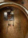
A couple of years back I picked up a free pair of KLH model 6s, which someone had tried to repair at home. The box and woofers were original but nothing else.
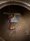
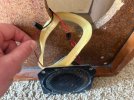
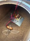
Recently my uncle moved and left me an extra pair of KLH model 17s that he no longer needed. It was my understanding that the only difference between these 2 models was the size of the woofer and cabinet. I moved the crossovers and tweeters over to the model 6 cabinets only to discover that the crossover designs were slightly different and that one of the crossovers was broken. The woofer was putting out sound but not the tweeter. The tweeter appeared to work fine when wired directly into the receiver so I assume it must be the caps.
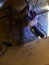
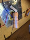
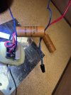
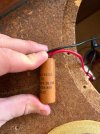
The brown cap and black cap variations seem very similar. Both have a cap that's wired within the 3 way switch and a cap that goes to the tweeter. The caps that go to the tweeters seem to both be 8 MFD (IMG_4013). However, the caps within the 3 way switches seem to be different. The brown cap says 2 X 2 MFD so 4 MFD total (IMG_4015).
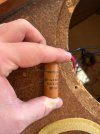
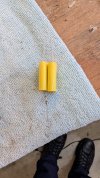
The black cap with the red ends (IMG_4017) reads the following:
Tennessee
Electronics
2 UF - 50V
MY-LYTIC
51-6718
2 UF - 50V

Do these crossovers even seem correct for the model 6? I find it weird that there aren't any inductors in the crossover.
If I'm buying caps to repair one speaker should I just replace the caps in both? Which design should I follow for buying replacements?
 

Attachments

  • IMG_3965.jpeg
    IMG_3965.jpeg
    100.4 KB · Views: 12
  • IMG_3964.jpeg
    IMG_3964.jpeg
    86.8 KB · Views: 12
  • IMG_4017.jpeg
    IMG_4017.jpeg
    120.9 KB · Views: 10
  • IMG_4016.jpeg
    IMG_4016.jpeg
    94 KB · Views: 10
  • IMG_4015.jpeg
    IMG_4015.jpeg
    101.8 KB · Views: 9
  • IMG_4014.jpeg
    IMG_4014.jpeg
    143.8 KB · Views: 10
  • IMG_4013.jpeg
    IMG_4013.jpeg
    103.3 KB · Views: 10
  • IMG_4012.jpeg
    IMG_4012.jpeg
    147.5 KB · Views: 9
  • IMG_3995.jpeg
    IMG_3995.jpeg
    161.2 KB · Views: 9
  • IMG_3966.jpeg
    IMG_3966.jpeg
    106.5 KB · Views: 12
Register to hide this ad
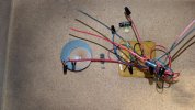
I am working on a pair of Model Sixes now. Mine have a single 8 uf cap and the double 2 uf cap(s). Those are two 2uf caps with one wire going in and two wires going out. They are part of the switch network. I wired my replacement like below. I have a pair of Model twenty threes that had a bad switch. I had to bypass it to get the tweeter to work.
PXL_20260403_203308977.jpg
 
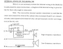
Here's the schematic for the Model 6:

KLH_Six_xo.jpg
There should be an inductor that's usually (EDIT: maybe it should say "sometimes?") found screwed to the inside of the front baffle along with the 8uf cap. The Model 17 has all the same crossover stuff but without the inductor on the woof. The switches can sometimes be problematic but if you soak the inside of it with "DeOxit" by pushing the bat handle IN toward the body of the switch and squirting the fluid into the exposed gap then exercising it, it should come back to life. Make sure to stuff the cabs with the fiberglass from the 17s if there was none left in the Model 6s. You might need some more. Be sure to get some of RoyC's magic butyl sealer as well. Good Luck!
-Tim
 
Last edited:
Here is a photo of one of my sixes. The inductor is on the left and the 8 uf cap is help by a clamp screwed in at the top of the photo. The double 2 up cap is encased in epoxy.
PXL_20260405_040442961.jpg
 
As simple as the Model 6 crossover is, one of my "early" ones with the epoxied in woofers came from the factory with the second 3 ohm resistor and the 7.5 ohm resistor swapped places. Guess nobody noticed for almost 60 years ... and if they did, when it's buried in a block of epoxy it's pretty hard to fix after the fact. Sounds nice now!
 
Here's the schematic for the Model 6:

View attachment 3734512
There should be an inductor that's usually (EDIT: maybe it should say "sometimes?") found screwed to the inside of the front baffle along with the 8uf cap. The Model 17 has all the same crossover stuff but without the inductor on the woof. The switches can sometimes be problematic but if you soak the inside of it with "DeOxit" by pushing the bat handle IN toward the body of the switch and squirting the fluid into the exposed gap then exercising it, it should come back to life. Make sure to stuff the cabs with the fiberglass from the 17s if there was none left in the Model 6s. You might need some more. Be sure to get some of RoyC's magic butyl sealer as well. Good Luck!
-Tim
There is the old inductors glued to the back wall of the cab. Are these pretty straightforward to wire back into the crossover?
 
Basically wire the coil in series with the woofer as shown in the diagram. Connections A & C are connected to the positive speakers terminal. B is connected to the negative speaker terminal.

Woofers almost always sound better with a series coil. Usually better with some amount of capacitor in parallel too.
 
Last edited:
Correction to the previous post - Connections B & C are connected to the positive terminal. A is connected to the negative speaker terminal.

The schematic is for the "original" Model 6 that had THREE speaker terminals on the back panel, marked "C" for the tweeter positive (through the resistor and capacitor network) and "B" for the woofer positive (through the inductor) along with the shared negative marked "A". This would allow one to use just the woofer or just the tweeter ... not really sure WHY, but there you have it.

Your parts have just TWO speaker terminals marked "+" and "-". In your case the "+" terminal is the same as having the old "C" and "B" terminals shorted together.

Confused? I hope not ...

P.S. Be sure to include the black or white "cheesecloth" to protect the back of the woofer from fiberglass pushing into the cone as well as fibers sloughing off and getting in the works.
 
Last edited:
Basically wire the coil in series with the woofer as shown in the diagram. Connections A & C are connected to the positive speakers terminal. B is connected to the negative speaker terminal.

Woofers almost always sound better with a series coil. Usually better with some amount of capacitor in parallel too.
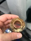
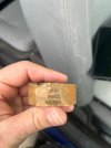
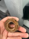
I used a heat gun to pull the old induction coil off the back wall of the speaker.
So I just connect the red wire for the woofer through this? Does direction matter?
 

Attachments

  • image0.jpeg
    image0.jpeg
    73.5 KB · Views: 5
  • image2.jpeg
    image2.jpeg
    61.8 KB · Views: 5
  • image1.jpeg
    image1.jpeg
    73.4 KB · Views: 5
Yup. Guess you're going to have to dig a bit.You shouldn't unwrap any of it if you can help it, just scrape a little of the insulated coating off the copper wire to get the solder to take. Direction doesn't make any difference.
 
Back
Top Bottom