• The move to the new server is done. There are some software and database maintenance updates in process. This has us passing the hat around to help out. We appreciate any donations. Seriously, even a dollar helps. The payment page may be found here - https://www.audiokarma.org/support.html

Klipsch Forte IV crossover values - Chart

BigRiver

Member
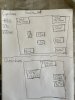
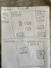
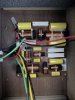
I opened up the Forte iv's and made a few images as well as a hand-drawn sketch for both the capacitor values and the resistor values. I could not really find this info anywhere and I was eager to know since folks seem to like to upgrade the heritage crossovers.

That said, I will probably not touch these for a few/6 months and if/when I do, I will either do one crossover and leave the other or I will just replace the small value capacitors first since I always notice the most in the tweets and especially the mids. I will replace with equivalent values.

I think I like the way they sound out of the box and want to live with it for a while and let them break in for 400-500 hours before doing anything. forte4-cross1.jpgforte4-crosscap1.jpgforte4-crossresistor.jpgforte4-valuechart1.jpg
 
Register to hide this ad
Is it possible to draw the schematic please?

I am sure it would be for many, but not for me.

I have not taken them out, the pics are still installed and so I have no idea what is connected to what and in what direction, etc.

In addition, since I have never drawn out a full schematic, I would not feel comfortable doing so for others. I could provide incorrect info that could potentially really muck things up for folks.

I also do not know the inductor values - removing and testing them is not an option for me - this is better left for someone with a tighter grip on this sort of thing.

I do plan to make more images once they are out of the cabinets that may be better able to illustrate the finer details.

My intention here was to provide cap and resistor values for those looking to upgrade those passive components and potentially get feedback from any that do.

Thanks!
 
More detailed pictures will be helpful if you have spare time please.

Thank you.
Yeah, this are the best I can do at the moment. They are installed in the speakers and I don't have any plans to take them out for some time. However, when I do I will definitely make more images.
 
Thanks for the pics and diagram. I will be getting a pair of these speakers in the not-so-distant future, I plan to upgrade the crossover at some point. Would be great if Klipsch would provide the inductor values, I'll probably try reaching out to them first, but something tells me they won't be into that. If not, I'll remove and measure each inductor and provide the info here. That will be months away though.
 
Thanks for the pics and diagram. I will be getting a pair of these speakers in the not-so-distant future, I plan to upgrade the crossover at some point. Would be great if Klipsch would provide the inductor values, I'll probably try reaching out to them first, but something tells me they won't be into that. If not, I'll remove and measure each inductor and provide the info here. That will be months away though.

I keep shopping for caps & resistors, putting them in their carts and then not checking out. I think because I also want to get another tube integrated first before putting more $$ in to these.

They are quite good as is but experience and the experience of others with heritage tells me significant upgrades can be had. In a very kind back and forth with Don Sachs he indicated that a set of Cornwall iv's redone with the V-cap odam and path audio resistors was night and day.

I guess the question I have regarding that are with the resistors since these are all 25W and the Path Audio are all 10W. I didn't get in to the weeds with him or check the values on the Cornwall but maybe a parallel or series installation of the resistors was used to get to 20W. I know the resistance effects the sound, so would going from a 8R ohm at 25W to an 8R ohm at 10W necessarily be a bad thing? Especially since they will be run with 15-30 wpc tube integrated.
 
When ready to rebuild I'd start w/ replacing the resistors w/ wire wound and the iron core inductors to air core (hard to tell what they are).
 
When ready to rebuild I'd start w/ replacing the resistors w/ wire wound and the iron core inductors to air core (hard to tell what they are).

Totally agree! I have been looking at both the Path and Dueland resistors as a possibility, The issue I am having is that the current resistors are 25W (which seems really high to me). Both the Path and the Dueland came highly recommended - especially so with the Path but they are both just 10W. Seeing as I am driving these speakers with lower powered tube integrateds (11-30wpc), can I get away with using 10W resistors?

If not those I can use the Ohmite Audio Gold resistors as well as I can find most of those in the values needed.

I would also like to replace the inductors with Solen air core but do not know the values and I am not exactly sure how to test for and determine those values.
 
The 10 watt Path Audio will be more the adequate.
Meniscus Audio can custom wind you coils at a number of different gauges for the same or less the Erse/ Jatzen
For caps- Jatzen Superior Z, or Silver Z depending on you end goals.
FIY.. those yellow caps are Bishop Elec entry level caps
Infinity used them.
They can sound a bit brittle at times.
 
Last edited:
The 10 watt Path Audio will be more the adequate.
Meniscus Audio can custom wind you coils at a number of different gauges for the same or less the Erse/ Jatzen
For caps- Jatzen Superior Z, or Silver Z depending on you end goals.
FIY.. those yellow caps are Bishop Elec entry level caps
Infinity used them.
They can sound a bit brittle at times.


Thanks, I figured those resistors would be fine. I was talking to an amp builder that re-did his Cornwall iv's with Path audio and V-Cap odam and could not recommend that combo enough.

I've used the Jantzen Superior Z and Alumen Z on some other projects and liked them.

Thanks for the tip on Meniscus Audio, I will definitely look into them. I just have to figure out the values first.
 
Thanks, I figured those resistors would be fine. I was talking to an amp builder that re-did his Cornwall iv's with Path audio and V-Cap odam and could not recommend that combo enough.

I've used the Jantzen Superior Z and Alumen Z on some other projects and liked them.

Thanks for the tip on Meniscus Audio, I will definitely look into them. I just have to figure out the values first.
You would think you could get a crossover schematic from Klipsch
 
The 10 watt Path Audio will be more the adequate.
Meniscus Audio can custom wind you coils at a number of different gauges for the same or less the Erse/ Jatzen
For caps- Jatzen Superior Z, or Silver Z depending on you end goals.
FIY.. those yellow caps are Bishop Elec entry level caps
Infinity used them.
They can sound a bit brittle at times.

Can I get your (and anyone else) opinion on the tolerance (+ or - difference on the values in ohms) on resistors. I ask this because it's tough to find exact drop in replacements that match values across one brand. For example the Forte crossover calls for two 8 ohm, one 5 ohm and a 13 ohm resistor. In this example Path audio makes a 5, but the other closest values are an 8.2 for the 8 and a 12 for the 13.

I can just run them in series if I need and add the values but would just use one when possible.
 
Can I get your (and anyone else) opinion on the tolerance (+ or - difference on the values in ohms) on resistors. I ask this because it's tough to find exact drop in replacements that match values across one brand. For example the Forte crossover calls for two 8 ohm, one 5 ohm and a 13 ohm resistor. In this example Path audio makes a 5, but the other closest values are an 8.2 for the 8 and a 12 for the 13.

I can just run them in series if I need and add the values but would just use one when possible.
The rule of thumb in the past was 10%.
Not sure if they are @ 3-5%.
Series should be fine-it just double the cost unfortunately.
IMHO you should really enjoy these-they seem a perfect match for a horn.
 
Last edited:
Base in the diagram can somebody identify please what are the parts (resistor and capacitor) in the signal path?
 

Attachments

  • forte4-valuechart1.jpg
    forte4-valuechart1.jpg
    101.5 KB · Views: 41
Base in the diagram can somebody identify please what are the parts (resistor and capacitor) in the signal path?

since that is only the parts, not the circuit, it's hard to know for sure. typically in klipsch crossovers, capacitors are in the signal path (in series) and resistors are not (in parallel). there are exceptions -- for instance, the chorus ii has a resistor before the autoformer that is in series. and the autoformers are in series . . .
 
Back
Top Bottom