• Please note that Audiokarma will be offline briefly for updates early on Monday morning, September 28th.

KR-8010 - 2nd Take

It’s scratchy when there’s sound, it cuts in and out instantly and for no reason, and does so independently for the left and right ears. Occasionally after some fiddling around with it both right and left work fine on FM and the sound quality seems ok to me.

I'm not familiar with the 8010, but this sounds like a dirty switch. I'd start by cleaning the selector switch. Not sure how sound inject works on this receiver - but on KR-6600/7600 it's tied to the tuner, so I'd clean both the switch and pot on that as well.
 
I'm not familiar with the 8010, but this sounds like a dirty switch....

Indeed! I did some more thorough testing while reading the manual (how novel), and I now believe that the audio problem was the result of a combination of a dirty switch, and the fact that I didn't know how FM muting worked.

There's a bad connection in a couple of different switches, most notably the Tone pushbutton, which toggles the Bass/Mid/Treble knobs. It is scratchy when I push it in, and when I put pressure on it in a certain way I can reliably cause it to crackle and drop the right channel altogether, just the problem I was experiencing, except now it only fails during the moment when I'm pushing the switch. I think this is a result of blowing out the massive quantities of dust and then working the switch a few dozen times, which probably had the effect of wearing through the crud to form a better connection.

Never having had a decent analog receiver, I wasn't aware that some of them had an FM muting feature. When I first tested the receiver, it was at the place of purchase, in a large city with a lot of strong FM signals, even without an antenna attached. Under this condition, I experienced the scratchiness of the switch, but could at least tune in stations. However, when I got it home to a smaller town about an hour away, there are no stations strong enough to overcome the FM muting without an antenna. At this point I could receive no FM stations at all, and being unaware of the FM muting feature, was worried that this was a more severe symptom of the same problem. Understanding this problem was made slightly more difficult because the Stereo indicator bulb is burned out. I was clued into the true cause when I turned off muting (i.e. switched to FM mono). Further discovering that while in muting mode the darn thing worked when I touched the antenna contact (and also discovering that sometimes it pays to read the manual), I attached an antenna–actually just a wire until I can get a proper antenna–and it works fine with the exception of a little scratchiness only when working certain controls.

The station indicator needle is within 0.1 MHz of true (good enough); I don't fully understand FM alignment but from what I've read in the forums it sounds like a needle that is pointing in a significantly wrong place can be a sign that someone may have been monkeying with the alignment. (Though maybe I misunderstood that.)

Now that I know it's useful to me in its current state, my servicing priorities have changed.
1. Clean the switches
2. Replace all incandescent bulbs with LEDs (most of them are burned out anyway)
3. Get a bajillion capacitors ordered and get to work on it

Gotta get me a desoldering station before I get to #3 I think. I would like to have one for work on the old Commodore computers anyway; it would help keep the ICs in those things cool when desoldering.

 
I am as NOOB as it gets.... but I can read, am persistent, not bad with mechanical solutions, have the right tools, & have the right mindset.

You can do this.

BTW = build a DBT. (don't die)

I am excited about your new journey and am hopeful for a positive outcome / experience.

:)

Thanks again for the encouragement.

I'll try not to die.
 
I know this is and old post but wanted to comment and ask a question.

I am doing Research on the Kr-8010 because i just picked up on of the hidden jewels this weekend. Going to start with a good cleaning of all the pots and switches and then an LED conversion. Lots of good information on this post.. Being a Noob with a little experience i research this forum at lot. Lots of good poeple willing to share their knowledge and experince.

My question in after reading this info on restoring the 8010is, what is changing the VRs mean? I cant learn if i dont ask.

Cant wait to start bringing this baby up to par like its glory days. it sounds really good now, but needs good cleaning and go from there...

This is my first post since joining AK about a month ago.
 
Okay... have rebuilt two of the 8010s.

Lost my picture hosting... I can recreate the build pictures, but will take time.

VR = Variable Resistor

Here are some pictures of my 1st KR-8010
PW20HtTZwDdJro1U4Fqo8IQXJ186gNKB9nJZ3WOZFkkbYHUTAsErnUrDxy6CDxK4iLhAqppZhn-p2eCLLHFWME26faPSv2FEFu3EX0H1nCbCBVCFZMw5lQqUbGw4Y_4X2HdKXSFP_LShrzqdMh48oiiiDCVGuHtDmwPnvVwqXivfRBKuLXaquokcHstghWBKvOEpXmJdiDxytyNA6O7O6JTMus3LTx7i84tfVhoYYPX-xjonanxhNqNqaSljpQG88GzryZU4ZyMkg62S0ff2BI3VOPu-LooN42SpwU1hyaIaIgrsBJlUq9N_BKWaHA2Era_qlYdFXsBNAAd64h276f8LrtHTsSo0eZ680ig3E3_bHFtsLHOFdU9rg89DdecUFzLyTxIIgQObkt2SC2XioS6fi1bur0iZTSEhqtmy_IninOe1YdEvxpTmOdvf9X89ZztruL_VkDCdvMaCCstQqaUDTGd2uqi7rlPOvcdzFh91TW8_3auueNOCRhk0uVnjExIlUzmp0rkBe_K0Gg-g_FFCTiNELAFxb_KqeLVBUvZZfjLMbnTQwrFjOEm_Uf38Z-OQeMzOAPrROzFJWG3LweZ-g1c9I51aMIf5Mv0r6WeiCiCIlSE2sluLdpycxLgjanTqgkJT_uhyLoV56qU1Lq36PVQfV2PkYNVB1P9JG6q_9xHo5kIUDN29mSUKGp-3AwstueX9fL2I2u_HfDbIkMZNSKFbH7a9QM02CGuhULNDcGcE=w1242-h933-no


B-MWR-gHQ95ohJQ3lSwGhq0s4whr6YjsXI0a3BGjUHHWGRw7lkCKKv44_Zmt-lEB_PdNVLOTPrqB-Gxchi3HoQdmWtFWEi85lG9svn_irWngKs6KsOB8zeueGiFO0Z6n0quB-uGwkgYzphRZJlEXW5xqsJM9e_2x7J1C1aluqcXQmZ-txKyIB1jPnt0Z77i7qD794n6YAwPiu78b7ouyA8bSC6UVMJ6Rixjgg4Fv8p4Sn91thLb0jAdJt3kmSFVFUxaY8Ny-Y5buKovy2ugVkDyzdKHX9FPdsou3ZYYT-ek8G6mSJhhBFnxw1GSE9t2Lr34neHdpWCanbskMLg_Iq6t4g_W3qjRkE5TKojFj2v0XA-Nqe8_wxAvgsmJgt6u1eV5cJDsyUqCTGEz8nGRr51N3IxfYNOZR-Av0AXN4hTES9JR-KQXkF03LGedsrj0-CDOuoDX7gZCAirb9V_uamrIRmtNPifZSLZiaTigrgA77svAB0WCAP9HnUxs3eVwNAWzg-N7Kepc9f_xnymzSjWpjn7kS5vOw0IRnEkkRB9eBHOUdiudGiFkdd10_B9uUXyppm1fxqGIMZtA03DBOf38QC_e_szbegax4TUGqjwVB5E328Sz8ECR2YGkWIxN8YO6y31oxMHUXYbefcVmVw49vSoCId-qUOBBR1OYyIt1a3lf8fjHDQUJZRG2dLS5Lg4pOw7WLQKmu86cVBgtd8PRTPOmQS8iGpexFYuZlSMSAa7UL=w1242-h933-no

Wa43Ed90PF3SR5TkfsAXJZ72wvF4VLPkfNhYX636KpHT4uKoIcooyuiyuE5N1_bcdZ1GE864kddA9hYSFNLFLFpwE1iBaFnVg8un0seqmMDkeUqG616XgK4wM9Cv5gia57eAwqL3iAmTQsFeKdECfblsfHtw01ZKBHfWXjZ1u7nkft_az3dtaKfu8G7vUkm9S44whYWTJjaxmOoejxWBlBJYnHqZdSzFsAoC56U12FksYX2AjgP5l7T1Vxc1VCq-iB15_AvdLsWV1UeJ0cPMj8guYwDZQ8RAG4vWhYOzr-apdwMf9Mt2UHdTbrrSpAoACbchP5LlsINz2WFqk-r98l1W15rYCDnbMWEYPnF92LZeR3CpHSljeJehdFKAFbH4opA25XFOYJdwpboFFiNB3EPI5QS12gx5ylBezgDUXDIhnHIcFoY0dK1gP4VI_AFZg6n97k6GE353jYc01KT7eBOi2mvRg6JCRtdQWMiXBnKBQpp-E5De0FPwHRJeovxhULGTcHa4Rh41ctbeS7ZUTJhvdmynm6RSwDaPykbJBp3lUi8AbYDjVWSLrjPaVrCTXVlS4AeQEXUrrkqj0_EWtSjzjFcrXp5L6BAFFTdLrkB8Un_7mTRZyjQa7CdPB2aA4K_14McfCZzxiVPr9gHTuCyAi_abV7RE5NiWPb94TpzoM7QUGO4YmSkGC6qMI83T0W9T8ddSuiRjbLjZK6gczIFUJzJU-NaF04r6pkzrqBjsFe0Z=w1242-h933-no
 
Last edited:
My machine is broken as I only see the last two pics from the OP in this thread. Just the two units and the pile-o-parts.
 
Thanks for getting back to me Super Noob, wow that is a good looking 8010! I love the blue LED conversion. Will have to look into the “VR” , variable resistor. It would help a look of folks when you get your picture postings back up. The pic you posted, is that everything you replaced or is that a kit?
 
thanks for the reply. I was just wondering as the first pic in the recent post was dead but the other two worked.
I just use ak, too stupid to figure out another way. Heck I haven't even started a media or an album.
 
SUPER NOOB, I've been all over the internet seeking someone like yourselves help! I LOVE the pics of the KR 8010! It looks brand new and I'm sure it sounds even better!
You see I have always wanted a monster receiver and finally got my chance to buy one. Some lady had it and the pictures looked like something I was looking for. She was describing it and then she mentioned how heavy it was, well I know to be a monster you usually have to weigh in at a good 40 or 50 lbs to meet that criteria and it did. She wanted $220 for it I said ok
I went and drove an hour away and she was right not only was it heavy but it was a BIG receiver! Real BIG! Long story short
I got it home and listened to it and I decided that I guess I never really owned a good receiver in my life because this thing was like going from driving a Nissan Sentra your whole life and then found a nice Lincoln Continental instead. Well, I was stoked...for a sec.
Until the selector knob all of a sudden froze up in a couple of turns and I couldn't turn it....Well, This is hard now for me to tell.
I decided somehow that I needed .... No, I didn't! I Panic'd. I freaked out! MY STEREO! This can't be happening! and in my moment of panic somehow I thought to force it might help and a pair of channel locks were within reach! I took the knob off and just began to turn and half the post came right off immediately! Once more...DONE! Sheered off right at the face! Just like butter! OUCH!
After composing myself I then was able to get more information on how I wasn't going to be able to find this part....But I DID! So I decided ok let's check this out and see if we can redeem ourselves for the original sin with the channel locks. So I saw that this selector switch had this weird wire piggybacked plastic thing on top of it and when I was taking it off one of the wires came loose so now I have two wires. Well anyhow, I studied the whole thing really well and saw that the very thin piece of metal must slip between the plastic pieces on top and that little metal tab that sticks up must fit through the middle of the thin metal strip right in the middle hole...fit perfect!
Ok so I got my 2 wires back as 1 piece, 1 short and 1 long. I disconnected the other side on the short one but left it hooked up to the far side on the long one. So I carefully and easily removed the face, was able to undo bolt holding switch in, removed it then put in the new one, no problem...going great in fact! Gonna take that wrong and make it a right! Next, I see how the little track things work and how you take that little metal tab sticking out on the ends of the wires or cables as I now think of them. And snap the pieces on....but the switch only turns so far or the light only lights up on part of them. So I moved the track and tried to realign but then it only goes so far the other way with different lights lighting up.
Now I did learn out of all this a few things and that's to not go too fast, don't lose your cool, back off if you feel like your sliding backward and I do....I feel I'm so close but if I keep jimmying this fine thin metal cable trying to crack the code of how this works I might overwork it! That is what I learned about painting too! Never overwork it because you can have a beautiful picture turn into a mud puddle in 2 or 3 strokes and I believe the same rule applies here. Should I have connected the wire to the switch before I put it in? Because I put in switch then connected plastic part with wire to it after...I just can't seem to get this little tab in the track correctly.Or its correct on one side but not the other! What is the trick? I wanted to be the MAN..Be WINNING! But No! I don't seem to be able to common sense myself through this part to get back to where I was, Enjoying my Lincoln Continental of stereos! Oh and the other thing is that when the light says FM is on I don't see the meter needles moving. Is there some kind of feature where the lids off it does not turn on FM Or? I don't know, It powers up lights come on If I move the track where the short side of the cable goes with the little tab it changes the lights....There must be an order to make this work out correctly. This was going so well and seemingly so simple what happened? Can you help? You posted the one that was in the fire and yours is exactly the same. 1 short 1 long. I'm chomping on the bit to get this thing purring away again but I am trying not to have it end up being more parts on the market for your projects not that I don't want to see you have them! OK I have overworked this note into a full-blown documentary So I'll let you go so you can work on other stuff but get back to me soon as your able and I'll just hold tight till then. I can send you pics if you want but doubt you need them. Thanks so much for reading and I look forward to hearing back from you as soon as you can. Im gonna hook up speakers and see if I'm getting any output anywhere in the meantime. Thanks! UuhhOohh
 
Not sure how to respond... still digesting that word salad.

:rant:

The selector switch is on a gear driven switch which relates the motion of the switch to a metal tape moving back and forth which slides a selector contact assembly at the back for the board. (if I remember correctly)

Never had a unit that was in a fire by the way... but have been tempted to throw a few in a fire in frustration. Not sure I can effectively talk you through your repair = mechanical fixes on the switches would be difficult for most.

Best of luck.
 
Super Noob

I followed your 2nd KR-8010 rebuild thread and used your parts list to rebuild my reciever. I'm the original owner of this gem. It had been collecting dust for several years waiting for a re-cap.

The 22,000 uf caps are no longer available so I went with 18,000 / 100 volt. They're basically the same size as the originals and fit snug into the oval clamp with the help of a couple pieces of thick electrical tape at the top of the caps.

I struggled with the (searched) biasing methods. Before rebuilding the output boards, I took voltage measurements at the 1k bias pot and found 1 leg to measure 50mv and assumed it to be the bias voltage. After removing the pots, I measured and recorded the resistance readings and adjusted the new pots to match the old ones and installed them. That method proved to get me very close to the original 50mv setting. I then fine-tuned them to achieve 50mv on that particular pot leg. I know this isn't the correct way to measure/set the bias, but measuring across the test point pins displays only a few mv. Is my bias method acceptable? The reciever sounds Stellar and the output transistor cases average 80 - 95 deg. F.

Can anyone guide me on my bias method?

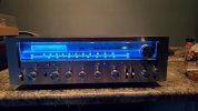
Dressed in blue.
 

Attachments

  • 20240616_193520.jpg
    20240616_193520.jpg
    70.2 KB · Views: 9
I have had my 8010 for so long, I forget when or how I came across it. I have had it in concert with my SX-1250 and it was equal in all respects.
 
Can anyone guide me on my bias method?

I haven't looked at a 8010 but setting bias looks pretty easy.
Adjust VR1 when measuring 50mV across pins 15 and 16.
Adjust VR2 when measuring 50mV across pins 31 and 32.

Did you read the service manual? Here is part of page 15.

1718590813471.png
 
I haven't looked at a 8010 but setting bias looks pretty easy.
Adjust VR1 when measuring 50mV across pins 15 and 16.
Adjust VR2 when measuring 50mV across pins 31 and 32.

Did you read the service manual? Here is part of page 15.

View attachment 3228214
I've tried that and only get a couple milivolts across those test points. I had similar readings before I rebuilt the unit. I wonder if the measurement has to be performed with an analog meter instead of digital?
 
Mea culpa

I turned the pots untill I achieved 50mv at the test points and voila!!

Still sounds Stellar and output transistor case temps are still good.

Thanks rickl for nudging me to give it another go.

HUGE SHOUTOUT TO SUPER NOOB!!!
Thank you for documenting your Kr-8010 rebuilds and sharing your parts list.

In 1980 I lugged this reciever, a Pioneer RT-1020l reel to reel, and a pair of HPM-100's to a party at a friend's house. I met the girl of my dreams that night. FF 44 years - We listened to it last evening and reminisced about that night. Now, if I could just rebuild her... Kidding!!!
 

Attachments

  • 20240617_085644.jpg
    20240617_085644.jpg
    141 KB · Views: 6
  • 20240617_085453.jpg
    20240617_085453.jpg
    124.8 KB · Views: 6
Last edited:
Back
Top Bottom