• The move to the new server is done. There are some software and database maintenance updates in process. This has us passing the hat around to help out. We appreciate any donations. Seriously, even a dollar helps. The payment page may be found here - https://www.audiokarma.org/support.html

KX-100 Project is my first Fisher Restore

richiem46

Retired and enjoying life and music!
Subscriber
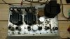
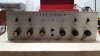
I recently purchased an KX-100 on Ebay and have begun cleanup and restoration efforts. I brought it up to 107VAC on a variac and the bios voltage settled in at about 41V so I stopped there. It looks like all the caps are original but nothing seems to be overheating and the unit plays surprisingly well given it's age and condition. So far I put in the 10 ohm cathode resistors and will add the 100 ohm screen resistors shortly. The 560 Ohm power resistor in the cathode/heater/bios is open so I'll probably replace that with the zener diode configuration. I don't want to do too much until I determine the state of the power supply electrolytics. Any suggestions are very welcome at this point. I'm not clear on now many of the capacitors in the signal path need to be replaced, I've read different opinions/approaches and I don't want to "fix" something that isn't really broken as the amp sounds pretty good even in it's present state.
 

Attachments

  • 20210327_174755.jpg
    20210327_174755.jpg
    66.9 KB · Views: 102
  • 20210327_174825.jpg
    20210327_174825.jpg
    110.6 KB · Views: 97
Register to hide this ad
There's a thread in the stickies that lists must do, should do and would be good to do projects. I suggest looking at those lists. I tried to find it for you but failed.
 
Last edited:
+1 on Thorne's suggestion to look at the stickies.

You've already started doing some of the recommended mods. Keep going.

I'd update the power supply caps, but that's just me. I've re-stuffed caps and used Hayseed caps. Either way is fine.

I'd put a CL-90 in-rush limiter in the hot leg of the primary to slow the current in-rush at power on and drop a couple of volts coming in. That will save your power switch long term.

BTW, the KX-100 is a nice amp. I have one myself. Good score!
 
The 560 Ohm power resistor in the cathode/heater/bios is open
I think that resistor is in parallel with 4 signal tube heaters, right? I wouldn't run the unit in this condition. This resistor limits voltage/current that flows through signal tube heaters and combined resistance in the output stage cathode sets it's bias. Too many things can go wrong if that resistor is open.
 
Guess I was fortunate in that I ran it unknowingly with the resistor open. I'm going to replace it with the 4 Zener diodes and the 10Ohn 1 watt resistor as I was planning on doing that anyway. Will also replace the 100MF capacitor that parallels the resistor while I'm at it. That should happen Monday when the resistors arrive. In the meantime I'll add the screen resistors as that seems prudent. The 7868's are branded Radio Shack so I'm not sure of their origins. We'll see how things develop. SO far I'm pleased it works as well as it does. I think I got a bit lucky with my purchase.
 
Last edited:
I'm not clear on now many of the capacitors in the signal path need to be replaced
Per 7868 datasheet, 330k grid leak resistance is at max. One of commonly suggested mods is to replace it with 220k but coupling cap capacitance need to be changed from 0.047uF to 0.1uF to maintain same time constant of the RC stage.
 
Per 7868 datasheet, 330k grid leak resistance is at max. One of commonly suggested mods is to replace it with 220k but coupling cap capacitance need to be changed from 0.047uF to 0.1uF to maintain same time constant of the RC stage.
I am familiar with these modifications and plan to implement them. What I am confused about is if capacitors further back in the signal path (phono and Tone control path) should be replaced. Any advice is welcomed, I want to optimize the amp's potential but not refurbish where the vintage components are functioning well.
 
Certain coupling cap types are automatically known as to be replaced because of the their reliability issues. Without in-circuit cap checker who knows if those are good. Some members here, who are familiar with this particular amp will make a suggestion. Most other caps are part of the PEC networks. Those are ceramic and those PEC's can be built with discrete and higher grade & tolerance components.
 
grind - Are you sure that .1uF maintains the time constant and not .68uF? I believe both are very close, but with my 7591's on my 500-C and 220k grid resistors, .068uF is closer. You may be right. I'm just checking.
 
grind - Are you sure that .1uF maintains the time constant and not .68uF? I believe both are very close, but with my 7591's on my 500-C and 220k grid resistors, .068uF is closer. You may be right. I'm just checking.

Thorne,

You are right the official number is 0.068uF, but it's fine to round up. I've seen that talked about a few times before.
 
grind - Are you sure that .1uF maintains the time constant and not .68uF? I believe both are very close, but with my 7591's on my 500-C and 220k grid resistors, .068uF is closer. You may be right. I'm just checking.
Thorne, you are probably right. It probably would be better in some units and 0.1uF in others, depending on how corner frequencies are spaced from each other from stage to stage. My 220k / 0.1uF suggestion came from Fisher 400 which uses same output tubes. I'm sure Dave verified this RC combination in his stability testing before posting it. In OP's unit it can be different though.
 
Packaged Electronic Component. Those resistor and capacitor networks in tone control and phono sections that are shown in striped boxes on schematic. They are encapsulated in ceramic material. Those PECs can be built using much better quality components. read Dave’s RIAA network revision first though. Different component values, if fully compatible with your amp.
 
Printed Electronic Circuit. It's those rectangular orangey circuits typically attached to tone controls (for bass and treble). They contain the components that implement EQ for example.
 
Printed Electronic Circuit. It's those rectangular orangey circuits typically attached to tone controls (for bass and treble). They contain the components that implement EQ for example.
Thanks! I see them on the schematic now. Will read up on it.
 
Here we go again. The KX-100 is Cathode BIASED as are pretty much ALL FISHER Integrated and Stand-alone AMPS. The Grid leak or Grid RETURN Resistors and caps DO NOT REQUIRE CHANGING to a lower value (resistors) or a comparable higher value (CAPS). Max Grid Resistance in Cathode MODE is 1 MEG OHMS, not 330k OHMS as in the FIXED BIAS Receivers. The only reason to change coupling caps and or Grid return (Grid Leak) resistors is if they are bad or OUT OF SPEC! This is per the the Tube DATA SHEETS for the 7591-7868-6GM5 Family tubes.

EDIT 3/30/2021: THE FOLLOWING IS FOR FIXED BIAS ONLY!!!!!
220KΩ and .068uf are the CLOSEST PAIRING to a 330KΩ and .047uf R/C Time constant with STANDARD C.O.T.S. (commercial off the shelf parts). the 200k to 220K / .1uf pairing is at least 10-20 years old and is further off than the 220k/.068. Dave did the math back in 2014-2015 to hopefully clear this up. And he stated that distortion could possibly go higher with the .1uf cap and if not that would be the highest value used at the time. The 220K/.068uf pairing works VERY WELL, uses C.O.T.S. parts and is a no brainer.

330K * .047 = 15,510 (original values)
220K * .1 = 22,000 1st iteration of change
200K * .082 = 16,400 Also used as a 1st iteration for a short time (around 2013-14)
220K * .068 = 14,960 LAST iteration.

To get any closer to the original values, you'd need .068uf and 228KΩ (15,504). As 228K is NOT a Standard value, daisy chains and stacked resistors result in a mess , and you won't hear the difference anyway.
 
Last edited:
Good that I have not installed the mods yet as it saved having to do it twice. To be sure I have things right I plan to:

Change C25, C27, C26, and C28 to 0.068 uF
Change R57, R59, R58 and R60 to 220k Ohms
as this represents the latest iteration found to be the most appropriate for the 7868 tubes in the KX-100.
Anyone need four .1uf caps still in their wrappers? :-)
Thanks!
 
richiem46. Post #17. No need to do this as the KX-100 is Cathode Biased. The Changes are Mandated for FIXED BIAS ONLY. POST #16 edited to reflect this as I saw it wasn't absolutely clear.

Fred; That would work as well. 220000 * .068 = 15368. Close enough for Gov't work.
 
Thanks for everyone's input. I really appreciate it but I al also quite confused! I was patterning my restoration on information in the thread "Fisher KX-100 (X-100-B) Restoration" and in other similar threads. They all mention the C25, C27, C26, and C28 and R57, R59, R58 and R60 changes as well as providing a mod to separately bias each output tube all of which I planned to implement. Now as I understand it the resistor/capacitor changes are no longer required as part of my planned modifications? I'll put down my soldering iron for the moment and wait to hear from you guys.:dunno:
 
Back
Top Bottom