• The move to the new server is done. There are some software and database maintenance updates in process. This has us passing the hat around to help out. We appreciate any donations. Seriously, even a dollar helps. The payment page may be found here - https://www.audiokarma.org/support.html

Lafayette LR-1500TA Silent

SmrtJustin

Active Member
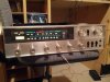
Hi guys, I'm trying to troubleshoot a Lafayette LR-1500TA that I just got. It powers up and lights up, but that's about all it'll do. No sound out of the speakers, and nothing from the headphones except a little white noise and a faint 60 Hz hum. I've tried all the sources, and the tuner also seems to be dead (tuning meter never moves, no stereo/accutune lights). I checked and there seems to be 70V to parts that require it, but I'm wondering if the 35V rail is working properly. None of the terminals of Q1 have ~35V of them like the schematic seems to suggest it should. None of the junctions of Q1 are shorted, but I guess that doesn't necessarily mean Q1 is good. Is there something easier I should check before pulling out Q1?

Thanks!
 

Attachments

  • IMG_20120328_204649.jpg
    IMG_20120328_204649.jpg
    80.1 KB · Views: 52
Last edited:
Register to hide this ad
I pulled out Q1 (2SD238) and testing with the diode function of my multimeter, it seems to be open between Base and Emitter. Is that a good enough test to consider it bad?

If so, can someone suggest a replacement? The original service manual recommends Motorola HEP241, which seems to cross reference to a NTE 175. I'd rather not use an NTE part if I don't have to.
 
Funny, I picked up one of these at a yard sale last year. It worked great for about an hour - then a pop, and nothing but a faint hum (I haven't powered it up in a while to see if the tuner gets a signal now, but I think the symptoms are pretty much exactly what you're describing). Where are you located? I'd be open to donating mine if any of the parts might help you get yours functional again. The only thing mine would be good for me for is to learn how to recap on a cheap receiver, which I don't know that I want to take the time to do right now.
 
Funny, I picked up one of these at a yard sale last year. It worked great for about an hour - then a pop, and nothing but a faint hum (I haven't powered it up in a while to see if the tuner gets a signal now, but I think the symptoms are pretty much exactly what you're describing). Where are you located? I'd be open to donating mine if any of the parts might help you get yours functional again. The only thing mine would be good for me for is to learn how to recap on a cheap receiver, which I don't know that I want to take the time to do right now.
Hopefully I've narrowed it down to that one transistor. Hopefully it didn't damage anything else when it went.
It seems to be a tough one to substitute. I'm located near Toledo, OH.
 
Would it be easier to come up witha TO-220 replacement? I'm sure I could get one to fit in there if someone could suggest one that would work in this application. If I switch to TO-220, I may also need a TO-220 equivalent for the adjacent 2SD236.
 
It ended up being that one power regulator transistor. I replaced the TO-66 2SD236 with a TO-220 TIP41C.

Now I just need to solve the slight hum and atrocious turn on thump (worse than any cap-coupled amp I've messed with). Hopefully a new power supply cap and coupling capacitors will solve the problem.
 
To set the bias current the service manual says to adjust a variable resistor to achieve 30ma on the emitter of Q8 and Q10. I was planning on measuring the voltage drop across an emitter resistor until I looked at the schematic. It appears this model the emitter is tied directly to ground.
How should I measure emitter current then? Desolder and use an ammeter, or is there a better way?
 
If it really calls for 30mA (not mV), you probably need to lift the resistor and insert your ammeter.
 
If it really calls for 30mA (not mV), you probably need to lift the resistor and insert your ammeter.

It does say ma. I just find it odd that the circuit design does not utilize emitter resistors.

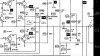
Edit: attached is a screenshot of the schematic showing Q8 and the surrounding circuit.
 

Attachments

  • Screenshot_2012-04-01-14-04-37.jpg
    Screenshot_2012-04-01-14-04-37.jpg
    119.4 KB · Views: 36
  • Screenshot_2012-04-01-14-08-51.jpg
    Screenshot_2012-04-01-14-08-51.jpg
    134.1 KB · Views: 27
Last edited:
Back
Top Bottom