• The move to the new server is done. There are some software and database maintenance updates in process. This has us passing the hat around to help out. We appreciate any donations. Seriously, even a dollar helps. The payment page may be found here - https://www.audiokarma.org/support.html

Lafayette LT-725 tuner problem

trkyle

AK Subscriber
Subscriber
Have a nice LT-725 tuner that i'm having a problem that has me stumped. Basically, the tuner receives FM well below about +/- 100MHz. above that the signal weakens quickly and stereo does not engage. It has a center/strength meter that appears to work well at lower frequencies. the tuning cap moves freely without physical abnormalities.

I have a Rohde and Schwarz SMG signal generator (similar to HP8657) and Sencore SG165 that can be used with the SMG to generate an MPX signal all through a balun to the tuner. I am able to inject the combined signal and monitor the output on a oscope. It generates a very clean 400Hz sine wave and the stereo light pops on when the dial is tuned to the RF level throughout the FM range. The meter strength and centering functions on the tuner respond well at low, mid and high frequencies with a threshold of ~ -65dBm at each frequency.

But when i swap this setup for a simple 300 ohm antenna i run into problems. stereo stations are picked up to about 97MHz but not above and the centering/strength meter tapers to off quickly at about 100MHz and i receive no stations above this level.

I have traced the LO 10.7MHz signal as far as the output of IC-102 but can see how the IF would discriminate between low and high RF's. Just can't understand what would account for this discrepancy between the SMG/SG165 inout and an regular FM signal. I haven't tried to adjust anything in the RF section as there isn't a service manual anywhere that i know of. thought someone here smarter than I might recognize this problem. I have a lot more info but trying to be focused...thanks

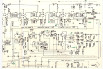
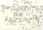
I've attached shots of the RF/IF.
 

Attachments

  • Screenshot 2026-09-26 at 6.38.24 PM.png
    Screenshot 2026-09-26 at 6.38.24 PM.png
    933.5 KB · Views: 7
  • Screenshot 2026-09-26 at 7.12.35 PM.png
    Screenshot 2026-09-26 at 7.12.35 PM.png
    932.8 KB · Views: 6
Register to hide this ad
all through a balun to the tuner

I don't have a clue, but just to make sure: you're confident that this setup is presenting the same impedance as the 300 ohm antenna?

You might want to consider asking this thread to be moved to the Tuners forum.
 
i believe so although the output impedance of the signal generator is 50 ohm. i don't think that the 50 vs 75 discrepancy makes any practical difference as long as i keep it consistent(?). i really think i'm doing something weirdly wrong though and thats a good thought. can i ask how to move this to the tuner forum?
 
how to move this to the tuner forum?

You should see a clickable called "Report". It sends a message to a moderator. In the message, just ask for the thread to be moved. It's probably best if you do the Report on the original post, but I don't think it matters a whole lot.
 
Might as well pose another stupid question - but a necessary one, maybe - before the real tuner experts weigh in. Have you checked that the same antenna gives good reception above 100MHz with another tuner?
 
I would clean the ground tabs on front-end first. There's a sticky at the top of the forum. Next adjust the trim caps to peak your signal at 106 Mhz and your coils at 90 Mhz.
 
That was my first thought, but on second thought, I decided it wouldn't explain the signal generator observations. On third thought, maybe the generator's output was strong enough so that the tuner was always being driven into limiting. I'm not sure how to interpret "threshold" in the OP.
 
by threshold i meant that the 1KHz sine wave appears to degrade at about the same output, the -65dBm, from the signal generator across the FM spectrum. the threshold for any wave is closer to about -80dBm and that also seems not to vary. could i ask how to find the 'sticky' for the ground tab cleaning? i've used a little CRC contact cleaner on the tuning cap but did not focus it on ground contact areas
 
by threshold i meant that the 1KHz sine wave appears to degrade at about the same output, the -65dBm, from the signal generator across the FM spectrum. the threshold for any wave is closer to about -80dBm and that also seems not to vary. could i ask how to find the 'sticky' for the ground tab cleaning? i've used a little CRC contact cleaner on the tuning cap but did not focus it on ground contact areas

Think you have bigger issues. That threshold should be much lower on both ends of the dial. I don't have the same generator, but I wouldn't expect mono signal to degrade until around 20 or below, stereo 30 ish. I'd inject 10.7Mhz at the beginning of the IF section and see how how your sensitivity is there.
 
The sticky is near the top of the forum list. (Hmm, I guess that's "by definition", isn't it?)

 
probably at the limit of my abilities here. i injected the 10.7MHz from the signal gen (50 ohm output impedance) via 0.01uF cap to pin 6 which is the input to IC-101 in the IF. the approx threshold at pin 9 at the input to the next stage IC-102 was ~ -60dBm. at pin 10/input to IC-103 the threshold fell to ~ -70dBm but at pin 11/input to IC-103 the wave was sharper, 375mV RMS and didn't move at all with the dBM at the lower limit of -135dBm. it also didn't change with any change dBm level. don't know what this means but seems...off. anyway, thanks for all the help here.
 
probably at the limit of my abilities here. i injected the 10.7MHz from the signal gen (50 ohm output impedance) via 0.01uF cap to pin 6 which is the input to IC-101 in the IF. the approx threshold at pin 9 at the input to the next stage IC-102 was ~ -60dBm. at pin 10/input to IC-103 the threshold fell to ~ -70dBm but at pin 11/input to IC-103 the wave was sharper, 375mV RMS and didn't move at all with the dBM at the lower limit of -135dBm. it also didn't change with any change dBm level. don't know what this means but seems...off. anyway, thanks for all the help here.

This actually sounds about right for the IF. You can take a scope and see the input and output of the IF chips to see if you have gain though the devices. Earlier you mentioned spraying the frontend and not the ground contacts. Contamination on the fins or liquid in the trim caps could greatly reduce your sensitivity. Once had a unit that some "cleaned" with WD40. A lot of compressed air, Isopropyl Alcohol and alignment brought it back.
 
I did try with CRC electronics cleaner but not very aggressively. after reading through the sticky note i'll try again with isopropyl/air and report back. thanks
 
I did try with CRC electronics cleaner but not very aggressively. after reading through the sticky note i'll try again with isopropyl/air and report back. thanks

Make sure your IPA is 99% or better. If not you will leave more contamination.
 
Back
Top Bottom