• The move to the new server is done. There are some software and database maintenance updates in process. This has us passing the hat around to help out. We appreciate any donations. Seriously, even a dollar helps. The payment page may be found here - https://www.audiokarma.org/support.html

Leak Stereo 60 Valve Amplifier

audioaaron

New Member
Hi all,

A good mate of mine was cleaning out the projection booth of an old theatre when he came across a Leak Stereo 60 Amp that was marked for the trash. He rang me to see if I was interested in it before he was about to toss it into the rubbish.... So I now have a Stereo 60 sitting on my work bench.

I've read a lot of posts about the Leak amps these amps on the web but not as much on the Leak 60 compared to the 20's and 50's although I believe the 60 to be similar to the 50.

I’m an electronic tech by trade and have worked in the field the last 10 years (mostly with solid state equipment) so I can work my way around a schematic. I’ve always loved vintage audio but don’t have as much experience with valve technology. I’m thinking about restoring this amp to use it as part of my home stereo system as reviews I’ve read about these amps seem quite exciting. Has anyone restored a Leak 60 or similar valve amp and would have any tips or tricks with what I could do to bring out the best in it? I’ve read both the pros and cons that oil filled caps are the way to go etc… being a valve amp I’m not entirely sure what the best thing would be to do. Any ideas? I plan to replace all the caps and resistors and have all the audio valves for this amp. I’ve been buying my replacement 600v + cap’s from eBay as they are hard to source here in Australia. Can anyone recommend an online store which is good to purchasing replacement parts for these sorts of things?

Many thanks all, any info would be greatly received.
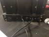
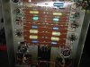
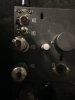
I've attached some images of the amp.
 

Attachments

  • 1.JPG
    1.JPG
    55 KB · Views: 295
  • 4.JPG
    4.JPG
    128.3 KB · Views: 198
  • 6.JPG
    6.JPG
    152.6 KB · Views: 297
  • 5.JPG
    5.JPG
    111.4 KB · Views: 327
  • 2.JPG
    2.JPG
    55.6 KB · Views: 198
Register to hide this ad
Aaron, your new toy looks Bad Ass :yes: Love the easy access and point to point wiring on the caps and resistors underneath.

At least check and or replace the coupling caps and check your bias voltage to start. The big can caps may be alright for now but long term they should be re-stuffed or replaced. Do you have a Variac to bring it up slowly?
 
Hi all,
Many thanks for the info!
I’ll check and replace all the Electrolytic caps as I’ve de-soldered checked most of them which appear to be over 20% out. Interestingly though, the non-electrolytic caps (with the exception of one completely open 0.16uF) seem to be pretty much bang on spec, but this could be a different story when under load. I’ll swap them out when I work out what the best replacement option is. The Electrolytic caps all appear to be multi-tapped, I’m not exactly sure of the availability of filter caps but I was thinking if I can’t find the original multi-can specs of 16 and 32uF values I could always increase the capacitance slightly as I’ve heard that this can be done in valve equipment (particularly in the power filtering section to improve filtering - as long as you don’t go ‘too’ high in valve ) But then again, is it better to stick to the original specified values on the schematic and keep values the same as designed by Leak or..... improve performance with improved components 
 
Has anyone restored a Leak 60 or similar valve amp and would have any tips or tricks with what I could do to bring out the best in it? I’ve read both the pros and cons that oil filled caps are the way to go etc…

After some deliberation we went with Orange Drops on my Stereo 20. It sounds wonderful. Your 60 looks very similar except with 34s rather than 84s. Here's some reading for you...

http://www.audiokarma.org/forums/showthread.php?t=429538

http://www.audiokarma.org/forums/showthread.php?t=432898

Congrats on an amazing scroe. I didn't think anything would ever displace my Marantz 2230, but the Stereo 20 did.
 
The big can caps may be alright for now but long term they should be re-stuffed or replaced.

Don't restuff or replace. Keep them in place disconnected so it looks unmolested, but wire tie new caps underneath (see threads linked above). One of the wonderful thing about those amps is that there is tons of room to do that.

I learned a TON watching my friend restore that amp for me, and I knew waaaay less than you do. I'm certain you will bring it back to it's full glory. Thank God your friend called you to save it from the dumpster.
 
Last edited:
I have heard good things about Orange drop caps but must admit I've never used them. They are easy enough to find online so I'll check them out for sure. Great work with your 20, it looks awesome! I wish mine had paint work as good as yours!
 
Those original caps appear to be Mullard "mustard" caps. I *think* those are polyester. If they are, they may be OK. I would test them at full rated voltage for leakage though before I trusted them. I've got some similar vintage film caps that are fine. ESR and value testers won't really put them to the test.
 
All the cap's on the phenolic board are not originals and were already replaced at some point, which is a good thing.(neat workmanship) I would not change them, especially the "mustards" which are very reliable and rarely fails. However, I would first concentrate on the (3) multi-section H.V electrolytic filter caps which looks original and will very likely fail, if they didn't already. Replace (or better, re-stuff to keep the original look) with good quality 500VDC elcap's) LEAK stereo 60 amps are rare and excellent sounding amps, they desserve a careful restoration job. Take your time, you won't be disapointed...
 
I thought that it might have been the case that the amp had partly been recapped previously as a couple of values were slightly different from what I found on the schematic diagram i.e .025uf on the schematic was .027uf installed. I'll order new caps for the Electrolytics. Is it better in Valve technology to replace Electrolytic caps with exact values i.e in this amp the values are 16uF, 32uF, 50uF OR is it preferred now days to increase all values slightly to improve filtering and performance? If so, how far can you go?

Thanks all for your help, I've learned a ton and starting to really love valve technology! I wish I was born 30 years earlier!
 
Some adjustment to reasonably obtainable values is usually fine. The only one you really have to watch is the first cap right off the rectifier. There are max values for the rectifier tube, and you should not exceed that for reasonable tube life. I wouldn't have much trouble going 33, 33, and 47 uf if this were mine though.
 
That's quite a score! Looks near mint! No corrosion, nice clean paint. Should shine & sound like a star when you're done!

Glenn
 
Audioaaron,

I would leave the capacitors be, provided they are not leaking. Yes, they have been changed; originals were TCC, mustard (and 'orange drops') are Philips - unless there are similar types manufactured elsewhere on the planet.

Mind that the power supply filter cap pairs are connected in parallel, thus you could replace by two single cans. If I may refer to circuit annotations (the schematic is available on internet), I would not make the input cap C12+C13 much bigger than 32µF, but you could make C14+C15 as big as is practical. (Caps those days were physically quite large; modern types can be higher value with advantage.) I am making frequent use of JJ 50+50 and 100+100µF/500V cans - quite decent looking. (No affiliation with JJ). Also mind that electrolytic caps are usually specified with some +/- 20% tolerance or more, so such deviations in your case do not necessarily mean bad caps. And modern electrolytics are quite sufficient for audio; don't waste money on boutique types. If you power up with the necessary care you might well find the mentioned caps still in good nic - but, as said.

Regarding the 'round' values of e.g. 0,25µF, you will no longer get those; most brands have changed to the E10 range, thus here 0,22µF etc. Then it could make sense to replace the resistors with modern 1% metal film types. R7, R10 should be low tolerance as they influence signal balance - as R12, R13 should be because they form part of the phase splitter load. (At present they are only +/- 10%.)

Good luck!
 
Hi Audiovet, many thanks for the time you have taken for the in-depth info, it's much appreciated and I'll put it to good use. I can't wait to have this amp up and running. My next challenge will be how to fix the paint work up without ruining the decals... It's a cold and rainy Saturday down here in Melbourne, perfect weather for spending time in the garage with the soldering iron! provided my wife lets me...
 
Wow NICE SCORE.. do power it up SLOWLY for the first time with just the rectifier… if the caps are getting bed ( in the PS section ) they will start getting warmish / hot. And you do NOT want one of the old big cans to vent on you… it's a stinky mess~

Mike
 
Well I’m done replacing all resistors and most of the capacitors in this amp (I’m still waiting for main electrolytics to arrive from the US – as they are on back order) I’ve cleaned the chassis up with a toothbrush and got rid of the years of dirt and grime. Unfortunately it has many scratches so I’m thinking about removing the transformers and giving the chassis a couple of coats of Hammer Tone paint which will unfortunately destroy the decals so I’m not quite sure what to do... I would like to have this as a show piece so I would like to re-paint it but hate to lost the decals. Can new decals be ordered or made? I’ve seen some posts regarding using a PC printer and then sprinkling some ‘decal power’ on the wet ink which will set can then be pressed onto the chassis. I would also like to replace the black transformer paper which is wrapped around the iron on the transformer, does anyone know what this is called? I had been toying with the idea of buying some black adhesive felt and sticking it on top to the existing transformer wrap paper. Will post some more pictures shortly.
 
Back
Top Bottom