• The move to the new server is done. There are some software and database maintenance updates in process. This has us passing the hat around to help out. We appreciate any donations. Seriously, even a dollar helps. The payment page may be found here - https://www.audiokarma.org/support.html

Leak Varislope II - Power supply?

audioaaron

New Member
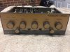
Last year a friend of mine saved a Leak Varislope 2 from the trash along with a Leak Stereo 60. Thanks to you guys on this site I was able to get the Stereo 60 up and running! :)

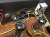
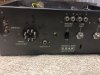
I've now had time to cosmetically (was an absolute mess) and electronically restore (replace caps and resistors) the Varislope 2 but I don't have a octal cable to connect the two components together. I was hoping to build a seperate AC power supply for this unit. Looks like i'll need 195V and 6.3V AC.

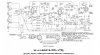
From looking at the diagram, I need

- Heater voltage 6.3V on Pins 4+5
- 195V on Pin 6.... BUT where would I connect the other voltage side of the 195V too? I've checked pin 8 and this is ground with the chassis...

Sorry if this is a silly question, I'm 6 months into loving my Valve amp restoration hobby and would love any advice as I would hate to destroy it or Electrocute myself..
 

Attachments

  • IMG_3497.jpg
    IMG_3497.jpg
    96.9 KB · Views: 48
  • IMG_3498.jpg
    IMG_3498.jpg
    85.1 KB · Views: 50
  • IMG_3499.jpg
    IMG_3499.jpg
    84.4 KB · Views: 38
  • Varislope II.jpg
    Varislope II.jpg
    69.6 KB · Views: 44
Register to hide this ad
The 195 volts has to be DC so you will need a high voltage diode/rectifier or rectifier tube when building a separate power supply.

If this is done and built, the 195 VDC (Volts DC) usually connects to the main filter capacitor of the preamp but I see you have a 47KΩ resistor right at pin 6 so you would put it at pin 6 before the resistor. This DC from the power supply is known as the B+ voltage input. After the voltage has been changed from AC to DC, the positive (B+) wire will connect to pin 6 and the other wire (B-) just connects to the chassis which is considered ground or chassis ground.

The 6.3 volts does not have to be DC as it is just for the tube heaters.
 
Last edited:
The negative side of the 195vdc supply is chassis ground. Looks like pin 8 on the socket.
 
The 195 volts has to be DC so you will need a high voltage diode/rectifier or rectifier tube when building a separate power supply.

If this is done and built, the 195 VDC (Volts DC) usually connects to the main filter capacitor of the preamp but I see you have a 47KΩ resistor right at pin 6 so you would put it at pin 6 before the resistor. This DC from the power supply is known as the B+ voltage input. After the voltage has been changed from AC to DC, the positive (B+) wire will connect to pin 6 and the other wire (B-) just connects to the chassis which is considered ground or chassis ground.

The 6.3 volts does not have to be DC as it is just for the tube heaters.

Thank you very much for this info! much appreciated everyone :thmbsp: this makes perfect sense to me now. I'll pick up a bridge rectifier on the way home tonight from atonics and hook it up to my variac for testing. I'm pretty sure I have a couple of 6-9 volt DC power supplies lying around I'll be able to use for the heaters. Might also pickup a metal box to house everything in. I hope these pre-amps sound ok :)
 
I would try to find a power transformer to do the job properly. Maybe look at Hammond or Heyboer transformers.
 
Back
Top Bottom