• Please note that Audiokarma will be offline briefly for updates early on Monday morning, September 28th.

Lepai Tripath LP-2020A+ mini Amp dissected

You have to be careful when dropping the gain by changing the feedback... this can sometimes lead to instability.

What is the gain of the original circuit, and what do you want to change it to?

-k

Correct me if I am wrong but it seems to me that the stock lepai much more gain than is necessary. If I input 2V peak-to-peak and look at the output across my 8 ohm speakers it starts to clip with the volume knob nowhere near full volume. Looking at the circuit on page 4 of this thread it appears that there is a gain of 6 or so from the op-amp and another gain of 30 or so from the TA2020. The TA2020 datasheet's typical circuit shows a total gain of 12 (Rf=Ri). So I'm not sure why the lepai has so much gain and it seems it could be reduced and still the amplifier would be fine with typical line level inputs. I was thinking reducing the gain to 1/3 of the lepai's stock gain. Either changing the op-amp gain or the TA2020 gain.
 
Correct me if I am wrong but it seems to me that the stock lepai much more gain than is necessary. If I input 2V peak-to-peak and look at the output across my 8 ohm speakers it starts to clip with the volume knob nowhere near full volume. Looking at the circuit on page 4 of this thread it appears that there is a gain of 6 or so from the op-amp and another gain of 30 or so from the TA2020. The TA2020 datasheet's typical circuit shows a total gain of 12 (Rf=Ri). So I'm not sure why the lepai has so much gain and it seems it could be reduced and still the amplifier would be fine with typical line level inputs. I was thinking reducing the gain to 1/3 of the lepai's stock gain. Either changing the op-amp gain or the TA2020 gain.

I don't know anything about the Lepai circuit. But I do know the Tripath pretty well, so if you can answer my question, I could suggest an approach.

-k
 
I don't know anything about the Lepai circuit. But I do know the Tripath pretty well, so if you can answer my question, I could suggest an approach.

-k

I haven't measured the gain of the Lepai so I don't know what it is either. I've only looked at the circuit on page 4 of this thread, and also verified with a scope that with 2V p-p input the output clips with the volume knob about halfway. So that's why I think the gain is too much and the schematic on page 4 seems to verify this.

In your experience with the tripath TA2020, did gain of 12 seem right (Rf=Ri=20K)? I can measure the Lepai's gain (ummodified) if it will help.

Also, I should not have said anything about speaker resistance - the issue is pretty much the same regardless of speaker resistance.
 
There's what looks like a 4.3K resistor connected to the inverting input of the opamp. I would try raising that to 22K. I think it would also be good practice to put a 1K resistor in series with the 33pF feedback cap on that opamp. I would guess that this is just about where you would want things, (assuming and audio taper pot, but let me know if you want to lop off even more gain.

Frankly, the way the tone control is implemented is rather problematic, and it makes it tricky to calculate the mid-band gain. In fact, I am not even positive that the tone control will be "flat" in the center position! Really, there needs to be a buffer between the tone stack and the Tripath. Otherwise, the output impedance of the tone circuit interacts with the gain set of the Tripath, and vice versa. If you don't need the tone control, I would pull those parts.

-k
 
Last edited:
Thanks Ken.

The newer Lepais have a tone defeat switch. So maybe I don't need to do anything to disable the tone section. Hopefully it is clear enough how that is implemented that I can get a handle on it, and maybe the TA2020 input will be more straightforward with tone defeat.

I will make some gain measurements with and without tone defeat and then think about best course to take with gain reduction. I think you are right that the op-amp circuit should be the first option. Unless the TA2020 gain is a lot higher than 12, in which case I might decide to bring it more in line with what is on the tripath datasheet.
 
Thanks Ken.

The newer Lepais have a tone defeat switch. So maybe I don't need to do anything to disable the tone section. Hopefully it is clear enough how that is implemented that I can get a handle on it, and maybe the TA2020 input will be more straightforward with tone defeat.

I will make some gain measurements with and without tone defeat and then think about best course to take with gain reduction. I think you are right that the op-amp circuit should be the first option. Unless the TA2020 gain is a lot higher than 12, in which case I might decide to bring it more in line with what is on the tripath datasheet.

Sounds like a good plan! BTW- I don't see any reason why the 2020 gain would be more than 12. As drawn on page 4, the total gain of the system, (not counting the tone control), would be almost 100... more than enough to render the volume knob insufficient in your case.

-k
 
Last edited:
As drawn on page 4, the total gain of the system, (not counting the tone control), would be almost 100... more than enough to render the volume knob insufficient in your case.

Indeed the total gain is 100 or more. About 6 in the op-amp circuit and about 17 in the TA2020. I want to make total gain about 30 (some reserve in case of low level sources) so I will do as you suggested and change the op-amp gain.

The tone defeat switch sends the op-amp output directly to a 2.2uF cap in series with a 15K resistor, into the TA2020 input (Rf=22K so gain is 17.6). So this is pretty much in accordance with the TA2020 datasheet, just a little more gain. I assume engaging the tone defeat completely disengages the tone circuitry since the switch is 2X SPDT. So I don't feel the need to do anything with the tone section, just use the tone defeat switch.

Besides the tone defeat, there is other circuitry different from the page 4 schematic. There are two dual op-amps. Maybe the other two amplifiers are used in the tone section. Maybe they gave you the buffer you wanted!
 
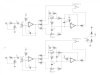
OK the op amp circuit on my lepai is different from what is shown on the page 4 schematic. On mine the the volume pot is a 20K pot in the feedback path in an inverting configuration, as shown in the attachment. So somehow I muffed the measurement - gain in this section is 20 with volume turned up all the way! So I replaced the 1K input resistor with a 7K resistor, and the 2.2uF cap with 1uF (did not have any values on hand between 0.1uF and 1uF in smd). Now the amp will still clip a 2V p-p input with the volume turned up to about 8, and it has some headroom for sources that are a little low on level, but not over-overkill like before.

Ken, what cap value would you use for the input cap that I replaced? Also, you said 1K in series with the cap in the feedback path, right? Is this a big deal? If not I won't bother as it would require standing the R and C components on end.

Anything else you would do? Thanks for your input!
 

Attachments

  • lepai input.jpg
    lepai input.jpg
    79.7 KB · Views: 24
OK the op amp circuit on my lepai is different from what is shown on the page 4 schematic. On mine the the volume pot is a 20K pot in the feedback path in an inverting configuration, as shown in the attachment. So somehow I muffed the measurement - gain in this section is 20 with volume turned up all the way! So I replaced the 1K input resistor with a 7K resistor, and the 2.2uF cap with 1uF (did not have any values on hand between 0.1uF and 1uF in smd). Now the amp will still clip a 2V p-p input with the volume turned up to about 8, and it has some headroom for sources that are a little low on level, but not over-overkill like before.

Ken, what cap value would you use for the input cap that I replaced? Also, you said 1K in series with the cap in the feedback path, right? Is this a big deal? If not I won't bother as it would require standing the R and C components on end.

Anything else you would do? Thanks for your input!

Hi... I am out and about today... I will reply to your questions either later, or over the weekend. Are you sure about that volume circuit? As drawn, the input impedance and the LF corner frequency will vary as the volume knob is turned, and can easily fall to very low levels.

-k
 
Last edited:
Ken: no hurry - please take your time. I appreciate that you would help on this especially since you don't even own one of these little lepais!

I can't be sure I've got every detail of the circuit correct (e.g. I had to solder leads onto the 2.2uF input cap to be able to measure it on my cheapo capacitance meter and so I could have wrong value for that). But I'm confident that I have the essence of the circuit. The potentiometer is definitely split such that resistance is variable both in the input and feedback paths. Maybe I should short out the pot terminals in the input path so that impedance is fixed in the input path, variable only in the feedback path?
 
I found the schematic, credited to Redshift187 from diyAudio, like the other one on page 4. So about what I sketched out for the volume circuit, and this is what I have on my Lepai.
 

Attachments

  • lepai full input.jpg
    lepai full input.jpg
    43.6 KB · Views: 65
Last edited:
And one more line of questions, Ken. Here are some distortion measurements made by user TMM on p26 of this DIY thread (hope it is OK to link to another forum)

http://www.diyaudio.com/forums/class-d/223389-lp-2020a-mod-thread-26.html

He lowered the gain of the TA2020 from 17 to 8 and seemed to get some better distortion measurements after doing so. So I am thinking it might be good to take out some gain there. I would make the TA2020 gain=12 as suggested on the tripath datasheet. Do you agree it might be a good idea?
 
Those distortion measurements don't make much sense, and I couldn't find any information about how they were taken. If you just run a tripath into a soundcard, you will not get meaningful results, because the input will probably be saturated by the clock signal. It is absolutely necessary to use a passive pre-filter and attenuator. Also, the distortion shown could well be coming from the mis-designed first opamp, at certain settings of the pot. All the change in gain seemed to do was to lower the output harmonics proportionally, meaning the error could well be in the first opamp. IE- Ignore the info at the link you sent me... it's rather vague and it doesn't look useful or possibly even correct. Sorry! It must be frustrating to try and work on this stuff when there is so much disinformation floating around.

I must admit, I am rather astonished at how the first stage was done. It is a very obvious mistake, that even a beginning engineer should have caught. It does not help to short out the pot... this will condemn the input impedance to ALWAYS be wrong....

Frankly, I would take this up with the seller of the amp. I mean, sure, you can start cutting traces and rewire the first opamp properly, but why should you have to??

-k

PS- I am firmly in the "all decent solid state amps sound the same below clipping" camp. Very unpopular with audiophiles, I know, but it is what it is.... However an amp like this will sound and perform like crap, and it is a bit amazing that anyone is using it happily! I mean, could it be that people who would freak out over using the wrong kind of cap in the signal path are listening to a badly defective amp and not noticing? Are you >sure< that circuit diagram is correct??
 
Last edited:
Thank you Ken. I am about as sure as I can be that the schematic has the op amp input as it really is on the lepai. It is pretty easy to trace it. Just to be clear, I meant I would short out part of the pot after changing the 1K resistor to 7K. If that is not good enough then I would be willing to re-wire the op-amps in a non-inverting configuration. I don't think I would get anywhere with the Chinese manufacturer - I doubt they'd listen to me as I'm not an audio engineer.

So any advice you have on a good (hopefully easy) approach to fixing the volume circuit would be welcome. I have already changed the input resistor and cap to 7K and 1uF and it sounds OK to me (I am just using a cheap computer sound card for source, maybe I should listen with decent a cd player), but I don't want to use the inverting circuit if it is badly flawed.

The funny part is I'll never listen to this after I'm done with it. This amplifier will end up in a yoga studio where my wife works - the source will be the teachers' phones. I'm just doing this for kicks.
 
Also, I don't mind changing the pot. So if input resistance needs to be more than 7K to make the inverting circuit OK then I can make it larger and change the value of the pot accordingly.

P.S. Do you hold the same opinion regarding DACs as you do for solid state amplifiers? I've concluded that the DAC in my TV sounds as good as anything else I own - so for convenience I typically play music HDMI->TV->amplifier.
 
You are one step ahead of me!

You did the right thing. (I am assuming you made R37 the 7K.) 7K is on the low-ish side for input impedance. Borderline, but it will probably be fine. It all depends on the ability of the device driving it. If it works, it works. (However, working with your sound card is not a perfect guaranty that it will work with some other source, so be sure to try it.) Another issue that I was going to mention is that raising the input resistor like that will degrade the noise figure of the amp, but we're talking about a few dB, way down at the lowest levels. Nothing that could possibly effect SQ in the intended application. So you are good to go! Nice job. (BTW- "7K" is a non-standard value. Just for the record, what is the exact value of the resistor?)

Now, let's look at the cap. There's no perfect answer here, because as the input impedance to the pot circuit drops towards zero, the high pass corner tends to infinity, with any size cap. The circuit relies on the fact that, hopefully, the signal is low enough in level by the time the frequency response degrades, so that you don't notice any problem in normal use.

The way I would deal with this involves a little bit of trial and error. I would try a cap that has 1/10 of the impedance of the 7K resistor at the lowest freq of interest. That should be plenty safe, but you can always change it if it proves unsatisfactory. So....

C= 1/(2*pi*700*20Hz)= 11uF... 10uF is the ticket. Adjust as needed if you want a different cutoff, or change the resistor. Again, the corner will still vary with the pot setting, but you have LOTS of margin with these values. Let me know if this works right, or not... (I'm ready for some much needed sleep, so it would be prudent to check my math and my logic!)

-k
 
Yes, the resistors I changed were R37 and the corresponding one on the other channel. Exact value was 7.15K (something I have on hand).

So I'm not clear about whether shorting the pot is good idea/bad idea? I guess from your point about the varying corner frequency that you would not short it?

I have 10uF caps in the right size. Just need to check the voltage rating. Is ceramic OK?
 
Last edited:
Again, just to be clear, when I say short out the pot, I am only talking about the portion that is in the input path. So short between pins labeled 2 and 3 in the schematic in post #92.
 
Best thing to do is to wipe off (SMD parts :-) of the entire Lepai tone nonsense circuit.
Read the Lepai Wiki in diyaudio.com.
These are Extremely poor amps in my experiences.
Quality and consequently sound is hugely variable unit to unit. Many are doa.
Often (usually :-) the Ta chip is a fake which doesn't help much at all.
IF you must have a ta2020 Get a YJ board ~15$ delivered on Ebay
Much simpler design execution.. it sorta follows the Tripath data sheet, whereas the lepai isn't even close.
Current cheapy chip amp boards (tripaths have finally run their course ) are a bit cheaper and perform better.. Do a little reading ?
 
Back
Top Bottom