


Max Pain
New Member
Hello,
I have Some vintage Levinson gear which had previously been converted to UK voltage. Now back in USA and assumed it would be easy to find information on how to return the jumpers to original US voltage configuration but have been pulling (what's left of) my hair out trying to find schematics or any clue. The preamp is a No. 28 with the PLS-228 Power Supply and the amp is a No. 23.5.
I was reading the thread http://audiokarma.org/forums/index....-repair-cap-choices-prices-avail-help.729776/ which contains an image of the same model Power Supply, which seems to show, in the upper left corner, a yellow jumper connecting pins P6 and P9 as well as a jumper connecting P7 to P4. The thread however, discusses a blown capacitor on the board and the origin of the Power Supply is unclear, so I'm a bit reluctant to copy the jumper configuration.
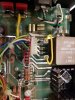
I've attached photos of my unit in case anyone needed to reference the UK configuration (230-250VAC). In the photo the red plug is disconnected for better visibility.
In this configuration P4 and P9 are jumpered and P17/P18, which are off to the side, are jumpered. The traces there don't seem to go anywhere so maybe P17 and P18 are just storage locations for the second jumper.
Can anyone confirm that for US input voltage (110VAC) the jumper configuration P6/P9 and P7/P4 is correct?
Any assistance would be greatly appreciated.

Cheers.
I have Some vintage Levinson gear which had previously been converted to UK voltage. Now back in USA and assumed it would be easy to find information on how to return the jumpers to original US voltage configuration but have been pulling (what's left of) my hair out trying to find schematics or any clue. The preamp is a No. 28 with the PLS-228 Power Supply and the amp is a No. 23.5.
I was reading the thread http://audiokarma.org/forums/index....-repair-cap-choices-prices-avail-help.729776/ which contains an image of the same model Power Supply, which seems to show, in the upper left corner, a yellow jumper connecting pins P6 and P9 as well as a jumper connecting P7 to P4. The thread however, discusses a blown capacitor on the board and the origin of the Power Supply is unclear, so I'm a bit reluctant to copy the jumper configuration.
I've attached photos of my unit in case anyone needed to reference the UK configuration (230-250VAC). In the photo the red plug is disconnected for better visibility.
In this configuration P4 and P9 are jumpered and P17/P18, which are off to the side, are jumpered. The traces there don't seem to go anywhere so maybe P17 and P18 are just storage locations for the second jumper.
Can anyone confirm that for US input voltage (110VAC) the jumper configuration P6/P9 and P7/P4 is correct?
Any assistance would be greatly appreciated.
Cheers.