jamesbytheba
New Member
Hi all,
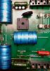
I have a Linn LP12 that I've owned for 31+ years. As has been documented in other forums, the early Linn Valhalla boards are prone to inrush surge damage, usually taking out the fuse, R1 and bridge rectifier BR1. The original installed Valhalla board, shown below, finally blew R1. Literally. As you can see, the inrushing power surge blew the top right off of it.
The sharp-eyed amongst you will also spot that this board is pre-Zener diode modification. In later Valhallas with the modification, the two zoners and resistor that make up the design improvement will be located in the lower part of the photo, between R38 and R3 in this photo.

This photo shows the damage done when R1 blew apart. The ventilation holes show the heat scorching from R2.

Others have also commented online about the 2.5W R2/R3 tending to overheat and age prematurely. As well, there have been claims of these resistors overheating and drifting in value, seriously affecting the PS' stability and overall performance. As you can see, these guys throw off a lot of heat, and over time, the exterior coatings are showing damage. I'll be replacing both of these resistors. This photo also shows the damage done to the smaller R1 a bit more clearly.
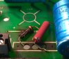
Conventional wisdom says to replace the wimpy 'lil rectifier with a beefier, more stable unit. Linn did. So I guess I'll replace that, too. In the Linn forums, many offer that replacing all of the electrolytics are an absolute must, because of age. Many opine that all of these caps must be replaced because they are "tired" and "worn out" and will cause great harm to...(fill in the blank). Hmmmm. I'm a little leery of those claims. Perhaps it's my limited experience working on these boards, but I see an awful lot of electronics from the late 60's, 70's, 80's (like this Valhalla), and 90's...that are working just fine, whose electrolytics are completely intact and functioning within spec.
Actually, I'm leery of most opinions expressed on the Linn forums. I guess I never drank the Kool-Aid. But that's an exploration best left for other forums or post.
At any rate, I'll do this repair and zener upgrade, an see what happens. If the old gal works, then, "yay!" If other problems crop up, then I'll cross that bridge when I get to it. And, if it turns out that caps are blown/blowing, then I'll happily eat crow and replace as many of those unreliable f***'g parts as it takes...
To recap, no pun intended, I'll be replacing:
R1 (40 ohm resistor) with an Antherm inrush current limiter, PN SG240
BR1 with a 6 amp 1000 volt Vishay bridge rectifier, GBPC610-E4/51
R2/R3 with 7W 15K 5% Vishay wirewound resistor, (see photo below for PN)
I'll also be adding the Zener Diode modification. This includes the following parts:
2 each: Vishay Zener diodes, 68Volt, 0.5 W
1 each: Vishay thin film resistor, 0.6W 12K 1%
I sourced all of these parts from Mouser electronics here in the United States. I don't remember what I paid for the entire lot, but it was around $7 or so. With USPS shipping, I paid a whopping $12. Mouser ships quickly, so I had my parts within 2-3 days of placing my order.
In order of work, then...
Starting with a new bridge rectifier, the mighty 6A 1000v Vishay. Surely it can handle things with a tad more
aplomb.
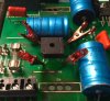

The new inrush limiter, the Antherm SG240:
Soldering in place:

This nifty little, circuit saving gem with Mouser part label:

And now, the 7W resistors. They can handle the heat better, plus they're a whole lot prettier. Yeah, I said that. Prettier.

Of course, caught up in my soldering frenzy, I forgot to stop and photograph the resistors luxuriating in their new board...but such is life. Maybe I'll get it right during my next project. Besides, you'll get a chance to see these forest green beauties later...
At this point, my repairs are made, and I should reinstall the board. I should also power it up...if it will at all...and check voltages at the motor connection, making adjustments as necessary. But, no, I'm not. Careless mook that I am, I'm going to proceed immediately to the fabled Zener diode modification.
So let's take a look at the Linn LP12 setup manual. I downloaded a 1998 copy from Vinyl Engine. (Thank you, gentle Vinyl Engine people who upload your vast store houses of manuals, catalogues, schematics and other ephemera. You all do the Lord's work.) You can find the Zener diode modification on page 47.
Looks like a poor man's square wave generator to me. Okay, I didn't come up with that one. See: http://www.electronics-tutorials.ws/diode/diode_7.html
First, mark the board where the mounting holes are to be drilled. You can see, faintly, the traces showing through from the other side. Before I drill anything, I double check the board, front and back, to make sure that I've correctly identified the right traces to connect with. Now, this board is not particularly complicated, but it's always good practice to measure twice and cut once. Sweet Jesus, how many times have I not followed that advice and made life more difficult for myself?!? Haven't we all?

Before I use a twist drill bit, though, I'm going to borrow a common work practice from our machinist brethren, use another tool to start the boring process. In this case, it's a conical diamond bit. A twist bit, as most of you know, wants to walk away from the initial point of the surface it's asked to engage. Since I want my through hole to exit the other side of the board centered on the trace, it's a good idea to take this precautionary step. The diamond bit can be pushed quickly into the somewhat soft surface of this board, with less wandering, cutting a perfect little pilot divot for the conventional twist bit which follows to complete the drilling operation.

More to come...stay tuned.
Cheers,
~james
I have a Linn LP12 that I've owned for 31+ years. As has been documented in other forums, the early Linn Valhalla boards are prone to inrush surge damage, usually taking out the fuse, R1 and bridge rectifier BR1. The original installed Valhalla board, shown below, finally blew R1. Literally. As you can see, the inrushing power surge blew the top right off of it.
The sharp-eyed amongst you will also spot that this board is pre-Zener diode modification. In later Valhallas with the modification, the two zoners and resistor that make up the design improvement will be located in the lower part of the photo, between R38 and R3 in this photo.
This photo shows the damage done when R1 blew apart. The ventilation holes show the heat scorching from R2.
Others have also commented online about the 2.5W R2/R3 tending to overheat and age prematurely. As well, there have been claims of these resistors overheating and drifting in value, seriously affecting the PS' stability and overall performance. As you can see, these guys throw off a lot of heat, and over time, the exterior coatings are showing damage. I'll be replacing both of these resistors. This photo also shows the damage done to the smaller R1 a bit more clearly.
Conventional wisdom says to replace the wimpy 'lil rectifier with a beefier, more stable unit. Linn did. So I guess I'll replace that, too. In the Linn forums, many offer that replacing all of the electrolytics are an absolute must, because of age. Many opine that all of these caps must be replaced because they are "tired" and "worn out" and will cause great harm to...(fill in the blank). Hmmmm. I'm a little leery of those claims. Perhaps it's my limited experience working on these boards, but I see an awful lot of electronics from the late 60's, 70's, 80's (like this Valhalla), and 90's...that are working just fine, whose electrolytics are completely intact and functioning within spec.
Actually, I'm leery of most opinions expressed on the Linn forums. I guess I never drank the Kool-Aid. But that's an exploration best left for other forums or post.
At any rate, I'll do this repair and zener upgrade, an see what happens. If the old gal works, then, "yay!" If other problems crop up, then I'll cross that bridge when I get to it. And, if it turns out that caps are blown/blowing, then I'll happily eat crow and replace as many of those unreliable f***'g parts as it takes...
To recap, no pun intended, I'll be replacing:
R1 (40 ohm resistor) with an Antherm inrush current limiter, PN SG240
BR1 with a 6 amp 1000 volt Vishay bridge rectifier, GBPC610-E4/51
R2/R3 with 7W 15K 5% Vishay wirewound resistor, (see photo below for PN)
I'll also be adding the Zener Diode modification. This includes the following parts:
2 each: Vishay Zener diodes, 68Volt, 0.5 W
1 each: Vishay thin film resistor, 0.6W 12K 1%
I sourced all of these parts from Mouser electronics here in the United States. I don't remember what I paid for the entire lot, but it was around $7 or so. With USPS shipping, I paid a whopping $12. Mouser ships quickly, so I had my parts within 2-3 days of placing my order.
In order of work, then...
Starting with a new bridge rectifier, the mighty 6A 1000v Vishay. Surely it can handle things with a tad more
aplomb.
The new inrush limiter, the Antherm SG240:
Soldering in place:
This nifty little, circuit saving gem with Mouser part label:
And now, the 7W resistors. They can handle the heat better, plus they're a whole lot prettier. Yeah, I said that. Prettier.
Of course, caught up in my soldering frenzy, I forgot to stop and photograph the resistors luxuriating in their new board...but such is life. Maybe I'll get it right during my next project. Besides, you'll get a chance to see these forest green beauties later...
At this point, my repairs are made, and I should reinstall the board. I should also power it up...if it will at all...and check voltages at the motor connection, making adjustments as necessary. But, no, I'm not. Careless mook that I am, I'm going to proceed immediately to the fabled Zener diode modification.
So let's take a look at the Linn LP12 setup manual. I downloaded a 1998 copy from Vinyl Engine. (Thank you, gentle Vinyl Engine people who upload your vast store houses of manuals, catalogues, schematics and other ephemera. You all do the Lord's work.) You can find the Zener diode modification on page 47.
Looks like a poor man's square wave generator to me. Okay, I didn't come up with that one. See: http://www.electronics-tutorials.ws/diode/diode_7.html
First, mark the board where the mounting holes are to be drilled. You can see, faintly, the traces showing through from the other side. Before I drill anything, I double check the board, front and back, to make sure that I've correctly identified the right traces to connect with. Now, this board is not particularly complicated, but it's always good practice to measure twice and cut once. Sweet Jesus, how many times have I not followed that advice and made life more difficult for myself?!? Haven't we all?
Before I use a twist drill bit, though, I'm going to borrow a common work practice from our machinist brethren, use another tool to start the boring process. In this case, it's a conical diamond bit. A twist bit, as most of you know, wants to walk away from the initial point of the surface it's asked to engage. Since I want my through hole to exit the other side of the board centered on the trace, it's a good idea to take this precautionary step. The diamond bit can be pushed quickly into the somewhat soft surface of this board, with less wandering, cutting a perfect little pilot divot for the conventional twist bit which follows to complete the drilling operation.
More to come...stay tuned.
Cheers,
~james