• The move to the new server is done. There are some software and database maintenance updates in process. This has us passing the hat around to help out. We appreciate any donations. Seriously, even a dollar helps. The payment page may be found here - https://www.audiokarma.org/support.html

load line thoughts?

gadget73

junk junkie
Subscriber
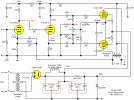
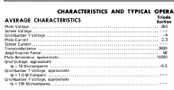
Messing with plans for a 6LR8 amp, and I'm starting at the voltage amp stage. Using the triodes in it which are similar-ish to a 12AT7, and planning to run it as a floating paraphase inverter. That may change to a split load, but the voltage amp will be the same either way.

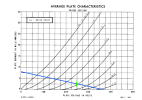
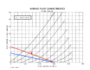
I messed with it last night with 47K plate resistors but I think it looks better with 27K. Thoughts? Blue line is 47K, red is 27K, the vertical bit is where I was thinking of idling it. Green spots are guesstimated voltage swing, approx 80v p-p. That should be considerably more than I actually need but may as well plan for some headroom. Realistic needs are probably closer to 40v p-p.

I was figuring on a 300v supply, not for any special reason other than it sounded like a nice round number. I can probably bump that up to 350 or so without any fuss.
1788870141595.png
 
Register to hide this ad
The blue line looks like more even input swing between the grid lines, almost exactly +/- 1V. That should equate to lower distortion.
 
my concern there was that its getting close to the curved part of the lines, but if thats not really a problem it should allow for more gain which isn't the worst thing. What I banged together last night came out just shy of 27 for gain.

Ideally I'd like to bias this with an LED, if for no better reason than its something I haven't yet experimented with. The ones I have per the datasheet are 1.8v, but the one I randomly grabbed last night is more like 1.5v. I'm not hard set on that idea, or that LED, it was just a thought and the part I happened to have in the box.
 
1788877223159.png

1788877265118.png

if I did it by datasheet stuff and used a 47K resistor to get a load 3x the plate resistance, that would need a 360v supply and would look like this

1788877572374.png

somehow that just seems too close to the non-linear cutoff area.
 
Last edited:
Not sure it is so much about getting into the curving area but rather do you get even swing around the OP for your input grid voltage. If you biased at the 2V grid line you would have a fairly symmetrical swing in between the 1V and 3V lines.
 
I'll see if I have an LED that runs a little closer to 2v and leave it with the 47K. The quick and dirty test I did last night gave about 0.9% THD, but thats with stuff laying on the bench in a maze of clip leads and components just hooked around the tube socket connections. I'm sure there was a significant level of noise in there.


How much current swing is needed?
If I can get 80v I'll be extremely happy, I think I will actually need maybe 40, so the idea is plan for a comfortable amount of headroom so I don't have to be excessively concerned about it. I haven't hooked up the pentode section yet, and the sheets only give stuff at 120v on G2 so I don't exactly know where the grid voltage is going to land. Planning for 400v plate and 300v G2.
 
If I can get 80v I'll be extremely happy, I think I will actually need maybe 40, so the idea is plan for a comfortable amount of headroom so I don't have to be excessively concerned about it. I haven't hooked up the pentode section yet, and the sheets only give stuff at 120v on G2 so I don't exactly know where the grid voltage is going to land. Planning for 400v plate and 300v G2.
No, I'm wondering whether a 5mA swing will be enough? Or do you need closer to 10mA? That will determine which line on the graph to use (red or blue).

:idea: :)
 
Ah, misunderstood the question

honestly I don't know, designing from load lines is very much not something I have deep experience with, hence the post. Most of my amps have been something of a cut and paste sort of affair, but I'm trying to do something a little more off the beaten path. I've looked at what others have done using this tube since it and it's compactron sibling the 6LU8 have been run in single ended amps, but the values others have chosen don't seem entirely right to me either. I've seen plate resistors ranging from 12K to 100K all with supply voltages around 300 and I just don't know what to make of that.
 
What tube or output device is it driving? Some need a larger current swing to reach their linear range. Others are not so fussy.

Just a thought.
 
Itself. 6LR8 triode section driving a second 6LR8 triode as a floating paraphase and a 6LR8 pentode. The other triode will just drive the second pentode.

The pentode is similar-ish to a 6CZ5 or 6973
 
Itself. 6LR8 triode section driving a second 6LR8 triode as a floating paraphase and a 6LR8 pentode. The other triode will just drive the second pentode.

The pentode is similar-ish to a 6CZ5 or 6973
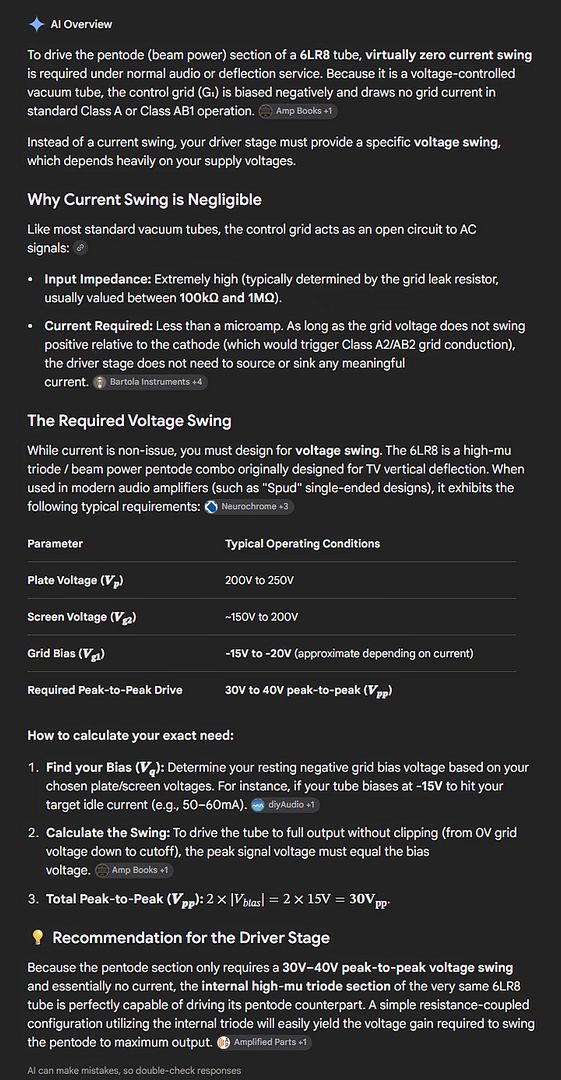
Hmm... Mr Google AI... it needs voltage-swing, not current-swing fussy. :thumbsup:


2394bf88-ccc9-4fe6-8740-9cdf28baf76f.jpg
 
Last edited:
yeah its just going to be cap coupled, nothing radical there. Haven't really put too much consideration to the pentode grid resistors, sheet allows up to 1M with fixed bias. Probably won't go that high, maybe 470K. Its also got the chain feeding the inverter so thats in parallel to the grid resistors. Currently those are also 470K so that ends up what, 235K or something? Not sure if it ends up being effectively lower than that since its negative feedback and all. I have room to tweak values, and none of this is set in stone.

link from that link, here is one with a 68K plate resistor for the voltage amp and 2mA idle from a 230v supply.


1788910114696.png

load line for the triode (also from that link)

1788910363174.png


so maybe the 47K isn't a bad idea.
 
I've used LED once for biasing a 6AU6 with 2mA current. Worked nicely.

Fixed bias effect, with infinite capacitor bypass. Can't get better with this.
I am happy with the result and sill use it today.

You just have to try different LED types to match your requirement. They are all different.
 
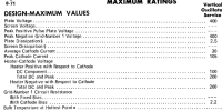
so I did some quick and dirty plotting for the pentode side. Plan is to run about 400 on the plate, and datasheet allows up to 300 on the screen. 14 watts / 400v = design max of 35mA plate current. 30mA seems like a not crazy idle point just to throw a dart at the wall.

30mA IA, 400v A, 300v G2, -49.4v G1
30mA IA, 400v A, 250v G2, -40.5v G1
30mA IA, 400v A, 200v G2, -31.5v G1

and this may very well end up idling lower, which would mean more voltage swing. 20mA at 400 plate and 300 screen is -52.2 volts
 
ok with a 47K plate resistor and an LED + 100 ohms (will be needed for feedback injection) I can get an easy 100v p-p without any signs of visible distortion so I think I'm OK here. LED runs 1.75v, cathode is right at 2v, so ~2.5 mA of current. Not where the load lines say it should be, but thats what it measures and ultimately I suspect thats the more critical value.
 
I've been very happy using broadcom HLMP-Q150 red LEDs in series with a small value unbypassed resistor to make up any voltage difference needed. All LEDs don't sound the same.
 
only reason I'm even using a resistor is I need somewhere to bring the feedback in. Plan is to share this LED for both triodes. One will be direct to the LED, the other will have a 100 in series with it. Depending on the particulars I might make that smaller just to minimize the difference in bias voltage between the two sections.
 
Back
Top Bottom