• The move to the new server is done. There are some software and database maintenance updates in process. This has us passing the hat around to help out. We appreciate any donations. Seriously, even a dollar helps. The payment page may be found here - https://www.audiokarma.org/support.html

looking for a power transformer for Philips Laboratories AH 578

senorderu

New Member
025_004.jpg Hello dear DIY in HIFI,

Everything is in the title, I'm looking for a power transformer for Philips Laboratories AH 578 to bring back to life my power amp.
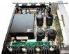
Sadly, I don't know anything about it and its specs. There is no information written on mine (the picture below is what I found on the internet to show you an example and also give you the opportunity to read the infos of the power transformer, the stickers are not on mine anymore).

It seems a bit hopeless but we never know.

Thanks for reading and Helping :)
 
Last edited:
Register to hide this ad
This what the repair man told me. But he didn’t seems keen to search for one.
Unfortunately this is often the favourite reaction from someone who isn't interested (or isn't skilled enough), in servicing your unit. They tell you the power transformer is faulty because they know this part is not available, and saying it is faulty excuses them from having any further involvement in repairing your unit.

If the unit is 'dead' for example (i.e. won't power on), there are numerous causes for this that don't involve the power transformer, power transformers in any case are not something which fails very often, only severe abuse will damage a power transformer. These people often hope you will just throw the unit away as 'electronic scrap' and buy a nice new unit from them at considerable cost to you.

I suggest you look elsewhere for a tech to repair your unit, and don't take any of this 'bad power transformer' nonsense from them. ;)
 
Last edited:
That’s what I thought either. The person was very unfriendly. So I picked up my power amp and brought it to another shop that seems more « professional ». I really wish that it was indeed an excuse not to fix it because I can’t accept to let my power amp dead ☠️ thanks for your answer anyway.
 
If you have the original part, transformers can be fixed, there are specialized techs who rewind transformers. If you find some place making custom transformers, for sure they can fix yours if needed.
 
honestly of all the things that are likely to fail in an amplifier, the power transformer is probably at the end of my "most likely to die" list.
 
I realize this is a relatively old thread. I am providing info to (hopefully) help anyone else. I just was given one of these, which will not turn on, meters dead, no lights, etc.. I also was afraid it was the power transformer. However, per the manual, all voltage sources are cut off until the touch switch on the front is on, which energizes one of many relays in this unit that allows it to power up completely. The lights for the front panel are derived from the output transistor voltages, so expect nothing from the amp unless you know the power switch circuitry is functional.

The protection board has a section that takes stepped-down AC from the main transformer and rectifies it to create a 12v supply for the power switch circuitry... that part of the circuit is always active. If you have 12v on one side of D103 on the front panel board or low voltage AC at pin 6 of J304 on the protection board I'd imagine the main xformer isn't dead. In addition to the power switch, the 12v powers the other TTL logic chips in on the front panel to 'remember' (but not really, since that part of the amp is never off if the switch on the back is on) the last state that they were in when the touch switch for mains power is turned off. The front panel light voltages aren't part of that circuit (else they'd always be on), they turn off with the touch switch power but the rest of the touchswitch circuit does not if the rear switch is on... therefore, again, if the touch switch isn't working, the amp is going to appear dead, and poking for voltages in the usual places a tech might expect isn't going to work on this one.

There are three ICs in the touch switch circuit. None of them are labeled, but as far as I can tell -and I should mention I am a hobbyist, not a tech- IC101 is a 4093 Schmitt trigger nand gate and the flip-flops at IC102 and IC103 are 4013s... the latter I base upon one of those ICs in mine not being the original RCA branded chips that have no ID on them, the former is based upon the manual calling them 'nand gates' and a google translation of a Dutch page referencing these units. I checked the transistor at Q1 to find out if it was driving voltage to IC101 when touched, and it is, but IC101 does not give the expected result based on its truth table (also tested out of circuit on a breadboard)y. I'll replace all of the logic chips and see what happens/report back, my order of those chips should arrive Sunday.

TLDR- I'd not take anyone's word re: the power supply without checking -at minimum- for the 12V at d103/low voltage AC at pin 6 of J304 on the protection board. Also, this amp is a bear to disassemble. If you do not like taking things apart or have a habit of losing small parts, take it to a tech.
 
Last edited:
Replacing IC101 and 102 allowed the unit to power on (partially) The LEDs on the front panel are working, the unit turns on and off and the main power relay energizes. I don't have meter lights working yet and the power transistors are out of the unit at the moment so I can't say if it's going to work, but the amp is no longer DOA. I would suggest investigating the touch switch circuitry on an amp that won't power on before doing anything else.

Also- the lights for the front panel aren't from the power transistors, those lights are from secondary taps on the transformer. The +/- 14.5 volts for the bipolar op amp supply is from the +/- 78v for the power transistors. Like I said, I 'm not a tech, I made a mistake there and didn't want to confuse anyone.
 
Further progress... meter lights are working now (it was just bulbs, standard wedge style bulbs like many other receivers of the time). I am only developing 1/2 of the 78v B+ supply and am therefore only getting +/- 7v at the supply lines of the op amps. I am now back to being concerned about the transformer, unfortunately... hopefully there's a short farther up the line that's pulling down the AC, although it's disheartening that it's the same on both channels and the 6.3 VAC is also low. I guess I'll check the circuitry that develops the +/- 14.5 volts out and hope the failure's in that, and if not, disconnect the AC from the rectifier circuit and see if I have 120 there (currently measures 60).
 
This amplifier has a soft start circuit - with a 22 Watt 1Ω resistor, you should check that the relay contacts for (relay K12) associated with the resistor are ok, and that the resistor itself is also ok. If the relay isn't closing - what you are seeing voltage wise (i.e. low) is perfectly possible.

The schematic helpfully (and usefully in this case), seems to indicate what I think are winding resistances for the transformer, and also for the relay coils (but surprisingly not for the transformer primaries).
There is an ancillary transformer that powers the protection circuit, and a low voltage connection to the voltage selector to power the above relay (K12).

I presume you have checked the voltage selector is set to your local mains voltage, and you have measured that this voltage is getting to the power transformer primary.

All of the above strongly indicates to me that the transformer is almost certainly OK, but is being affected by a malfunction elsewhere.

I'll leave you with those thoughts, I have never worked on Philips gear so I don't know specific information, good luck with it. ;)
 
Last edited:
This amplifier has a soft start circuit - with a 22 Watt 1Ω resistor, you should check that the relay contacts for (relay K12) associated with the resistor are ok, and that the resistor itself is also ok. If the relay isn't closing - what you are seeing voltage wise (i.e. low) is perfectly possible.

The schematic helpfully (and usefully in this case), seems to indicate what I think are winding resistances for the transformer, and also for the relay coils (but surprisingly not for the transformer primaries).
There is an ancillary transformer that powers the protection circuit, and a low voltage connection to the voltage selector to power the above relay (K12).

I presume you have checked the voltage selector is set to your local mains voltage, and you have measured that this voltage is getting to the power transformer primary.

All of the above strongly indicates to me that the transformer is almost certainly OK, but is being affected by a malfunction elsewhere.

I'll leave you with those thoughts, I have never worked on Philips gear so I don't know specific information, good luck with it. ;)

Thank you for taking the time to reply, I do appreciate it. I should mention that I have the pre-driver boards disconnected from the unit and am running it on a DBT. The relay coil resistances and the winding(?) resistances match the schematic. The 1 ohm resistor reads OK and K12 does click on after k11, although I have not taken it apart to verify the contacts. When the unit is powered on with the touch switch, the AC at the fuse drops to about 60v. I do not know why yet. The DBT is glowing, not brilliantly, but more than I'd expect based upon working on other gear. I see the voltage selector on the schematic, but I do not see one in this unit (the schematic indicates it is one of the first things inline w/the AC, it appears absent unless hidden.

There are two wires which come form the +/- side of the r. channel bridge rectifier that go to the front panel board. I unsoldered those as I assume that should remove the components downstream from the power supply, but no change.

Thanks again for your time. I'll investigate that relay more fully.
 
I could not find any obvious fault in the power supply or surrounding circuitry. I began to suspect that the dim bulb tester itself could be the issue. This amp has a 10A main fuse as well as a 15 amp internal fuse, 2 - 3x more than I've seen in the receivers I've worked on before which have been 120 WPC max; this is 210 WPC, and if some reports are to be believed, 300 WPC. Because the 40W bulb wasn't particularly bright, I went ahead and tried it without the dim bulb tester. Nothing blew up, and I now have the +/- 78v to the front board assembly off the r. channel filter cap. The 'filter' touch switch, which was not working previously, is now working, so I don't think I damaged the circuitry that's fed by that 78v but I have yet to test the bipolar supply for the op amps. Once I check that and finish recapping the front assembly board, I'm going to visually inspect and likely recap the driver boards, test the transistors on the driver boards for shorts, re-grease and re-install the power transistors and see what happens.

I am really impressed by the overall build quality of the amp. It is overbuilt, it uses a billion torx type screws in its construction, when it is put together it is a tank. The circuit board silkscreening is really helpful. That said, it is an absolute beast to try to move around on the bench and it has the type of construction that I have come to dislike where, as opposed to most Japanese receivers, things like the output transistor heatsink heatsink assemblies are an interral part of the chassis, as is the front panel, so you end up with a heavy, floppy mess when it's partially disassembled vs. the 'take the hood off' approach that most others often used... SAE also did this on some of their stuff. I found the matching AH5721 preamp -funny story on that if anyone's interested- so I went ahead and bought it, maybe getting ahead of myself, to have the set.
 
Last edited:
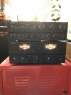
Victory... for now, anyway. It needed IC1 and IC2 on the front board assembly replaced, I re-greased the OTs and set the bias... it's been powering a set of Kef 107s for an hour or so... so far so good. Preamp's nice as well, I enjoy that you can select either or both (or none) of the outputs. The power amp has the most fun meters I've had on a piece of gear.
IMG-3213.jpg
 
Just bringing this back for a quick question..
Did you mention your mains fuse from line voltage was 10a ?? I'm working on a unit that is blowing my fuse on the back but it's only a 5 amp fuse?? Wondering what's what on this guy..
 
Just bringing this back for a quick question..
Did you mention your mains fuse from line voltage was 10a ?? I'm working on a unit that is blowing my fuse on the back but it's only a 5 amp fuse?? Wondering what's what on this guy..
Hey, the back of the amp says 10 amp slo-blo fuse.
 
Back
Top Bottom