SilentHatch
New Member
Greetings All,
Been doing some reading over the last months and year since I joined. I purchased an M-70 restore kit from eBay in hopes of repairing this device (in protection), but I just do not have the time, so I'm willing to spend some money on it since I spend the rest of my time working.
Some background, my dad got a C-70 / M-70 preamp/power amp combo with Magnepan MG-I speakers (no stand, so anyone that has a lead on those, let me know) back when he was in the Army.
He gave them to me (working) in 2011 timeframe and they worked but I moved out and they went into the basement. In any case, that's when the M-70 stopped working and I haven't had the time or monetary means to rectify the issue yet, and I've moved a couple times since then with the C-70 working (not in protection) and M-70 not working (in protection). I picked up the T-70 last year for a great price since I also like listening to the radio. Both the T-70 and C-70 work, as I can hear the radio coming out of the C-70.
First, I'm located in southern Maine, and I don't mind driving if necessary.
Second, it would be neat if there were someone from AK local that could look this over for me (paid, of course) and restore to working order.. or hold my hand as I look at it.
Third, I looked on Yamaha's website for authorized dealers and the closest is 70 miles (one-way) and their website mentions nothing about repairs.
I have a multimeter, some old janky soldering iron that I don't think actually works, and a 20 year old roll of solder. Sure, I could try to do this myself but the probability that I make the situation worse is.... likely. But if you want to hold my hand as I try to do it, sure. I'm home today/tomorrow and can take a look at stuff (or run to the nearest big box store to try to get some stuff).
In any case, I'd like some advice from you all or maybe someone in the area to see if they could take a look at it. And if anyone knows some good bookshelf or good tower speakers (been eyeing those klipsch tower speakers that have been on sale for like $249) to put with this, please share.
All advice appreciated.
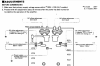
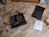
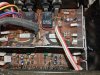
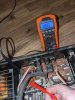
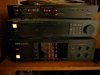
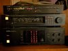
I've tried to include some pictures that I just took a moment ago (just plugged in for the first time in a while, and turned on). Last time I had it working, all the volume level indicator LEDs in the center panel worked on the M-70 still.
Respectfully,
SilentHatch
Been doing some reading over the last months and year since I joined. I purchased an M-70 restore kit from eBay in hopes of repairing this device (in protection), but I just do not have the time, so I'm willing to spend some money on it since I spend the rest of my time working.
Some background, my dad got a C-70 / M-70 preamp/power amp combo with Magnepan MG-I speakers (no stand, so anyone that has a lead on those, let me know) back when he was in the Army.
He gave them to me (working) in 2011 timeframe and they worked but I moved out and they went into the basement. In any case, that's when the M-70 stopped working and I haven't had the time or monetary means to rectify the issue yet, and I've moved a couple times since then with the C-70 working (not in protection) and M-70 not working (in protection). I picked up the T-70 last year for a great price since I also like listening to the radio. Both the T-70 and C-70 work, as I can hear the radio coming out of the C-70.
First, I'm located in southern Maine, and I don't mind driving if necessary.
Second, it would be neat if there were someone from AK local that could look this over for me (paid, of course) and restore to working order.. or hold my hand as I look at it.
Third, I looked on Yamaha's website for authorized dealers and the closest is 70 miles (one-way) and their website mentions nothing about repairs.
I have a multimeter, some old janky soldering iron that I don't think actually works, and a 20 year old roll of solder. Sure, I could try to do this myself but the probability that I make the situation worse is.... likely. But if you want to hold my hand as I try to do it, sure. I'm home today/tomorrow and can take a look at stuff (or run to the nearest big box store to try to get some stuff).
In any case, I'd like some advice from you all or maybe someone in the area to see if they could take a look at it. And if anyone knows some good bookshelf or good tower speakers (been eyeing those klipsch tower speakers that have been on sale for like $249) to put with this, please share.
All advice appreciated.
I've tried to include some pictures that I just took a moment ago (just plugged in for the first time in a while, and turned on). Last time I had it working, all the volume level indicator LEDs in the center panel worked on the M-70 still.
Respectfully,
SilentHatch