• Please note that Audiokarma will be offline briefly for updates early on Monday morning, September 28th.

Looking for help please on fixing the damage I did to my amp...

Confusilated

New Member
I just got a Pioneer SA-710 amp and after cleaning the pots, it tested perfectly. Unfortunately I didn't notice that the speaker wires were not inserted in the connector as far as they should have been, or the wire was stripped more than it should have been...in any event, the exposed wires apparently touched each other for a few seconds while I was turning up the volume. I heard this "clipping" sound and then nothing. The fuse didn't blow, there is still power going to the unit as the power light and the LED panel both illuminate, just no sound. I turned it off and back on again and don't hear the protection circuit breaker "click" anymore. Just wondering if this is possibly an easy fix related to that protection circuit or if I may have done severe damage to it? Any thoughts? I'm obviously not good at repair (I'm apparently very adept at ruining perfectly good gear) but if it's something relatively simple I'd try it. Nothing looks burnt on the boards that I can see..
 
Register to hide this ad
Hmm, depends how you define "easy." If the protection circuit isn't pulling in, I doubt it can be fixed without some diagnostic work and a multimeter at the least. If I were you, I'd start with pulling the output transistors and diode testing them. You'd probably get a better response in the Pioneer sub-forum, there are some experts over there who regularly help users out, including @merlynski
 
Speaker wires shorted: dead output transistors (and sometimes a few more parts). They can't survive to that.

You need a multimeter, a soldering iron, some basic skills and tools, and ask here and wait for instructions.
 
Thanks @merlynski, working on getting the DBT together. I wont be able to work on this until the weekend. I asked the moderator to move the thread as was suggested. I don't even know where to start. I'm ambitious and would love to be able to take a crack at fixing this as well as a couple of other pieces of vintage gear I have laying around, but I'm a novice to repair and I'm not sure anyone would have the patience to work with me on it. If there was someone in the Los Angeles area that would be willing to help, that would be great. When people ask for help and they have no experience, where DO they start? It has been suggested that "I'd start with pulling the output transistors and diode testing them", but I have no idea which ones are output transistors or what diode testing them even means : ( I do appreciate the input from those who have replied
 
Output transistors are the big transistors that provide the final stage of amplification, they generate a lot of heat so you'll always find them mounted to a heatsink. On this unit, looks like they are underneath the heatsink and soldered directly to the PCB, which is annoying.

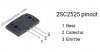
With regards to diode testing, it's always a great place to start when you have a catastrophic failure like blown fuses/no sound. All you need is a multimeter with a diode test function, or just resistance is fine too, but diode test is ideal. If you don't have a multimeter, you'll definitely need to purchase one, it's the main essential tool (along with DBT). This is my favorite article on diode testing BJTs: https://vetco.net/blog/test-a-transistor-with-a-multimeter/2017-05-04-12-25-37-07. It's probably better to remove (desolder) them for testing, especially if there's any ambiguity, because the surrounding circuitry could give you a weird reading that may be hard to interpret if you're new. Here are your transistor pinouts:
sa1075pinout.jpg
2sc2525pinout.jpg
 
They start just like you are doing. You build a DBT, acquire a Service Manual & Schematic (easy free download from hifiengine.com) and get a digital multimeter. You will want one that has a low voltage scale, DC & AC, that can measure down to 1mV (0.001 volts). I don't like autorange meters because they are confusing for new users. Many multimeters have a 'diode test' range, among others. $20 to $50 price range is usually a good choice. Fluke is probably the best brand but they can be pricey. You will need a good soldering iron, a roll of good solder (I recommend 63/37 rosin core from Kester), and some solder wick. Amazon carries all those items.
You have an exciting learning curve ahead of you.
There are a set of training documents from the US Navy that will help you learn: http://www.compatt.com/Tutorials/NEETS/NEETS.html
Modules 1, 2, 3, 4, 7 and 8 are most applicable for a start in vintage repair. You will understand what a diode is, and how 'diode testing' applies.
Here are a couple of other links:
So You Want To Repair Audio gear, Eh? Here's the tools you need... | Audiokarma Home Audio Stereo Discussion Forums
Skip the most expensive items in that list for now.
The Idiot's Guide to Using DeOxit (revisited) | Audiokarma Home Audio Stereo Discussion Forums
Scroll down on this page and download the 'Pioneer - Tuning Fork' PDFs:
http://www.cieri.net/Documenti/Altri marchi/FileList.html
Good luck and welcome to Vintage Audio Repair on Audiokarma, it is habit forming!!
Keep asking questions!
 
Thank you @merlynski for your informative post. Looks like I have my work cut out for me. With the holiday I have been out of the loop, but just saw your post and will start reading up on the resources you have provided. I hope I can hang with it. I am sure I will have lots of questions, it's what I do : )
 
Back
Top Bottom