xoaphexox
Supernatural Anesthetist
Hi all,
I've spent many hours trying to debug this issue and I am almost ready to throw in the towel. I am generally a parts replacer but am eager to learn and have a good foundation of what the different components do individually and have learned general troubleshooting procedures but am not yet at the point where I can determine what is causing this issue.
I bought this amp knowing that there was a 'scratchy' channel. Lo and behold the deoxit was not the solution - I should be so lucky.
Anyhow, here is the schematic for those interested in helping me out:
https://home.comcast.net/~devanymarino/LUXMAN_L80_L80V.pdf
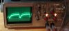
Symptom: Right channel sounds like crap (very distorted - see image). The left channel sounds wonderful.
Here is what I know:
1. When injecting a 1khz sine wave in the AUX input the output waves looks beautiful through the preamp and tone controls. I checked this by hooking my scope up to pin 1 (which I believe is the input from the pre to power amp - there are no jumpers on this integrated).
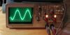
2. The output of the left channel wave is beautiful (see photo)
3. The output of the right channel is very distorted (missing peaks)
4. The DC offset of both channels has been dialed down to zero in both channels
5. The voltage taken from the collector of all four output transistors is a solid +/- 46V
Based on what I know of things I figure there is an issue supplying + voltage to some part of the right channel driver board. I am assuming this because the top half of the peaks is missing. This service manual sucks.
Here is what I have done so far trying to fix this issue:
1. Replaced every electrolytic capacitor in the unit (even the ripple filters - there is no AC ripple)
2. Replaced every transistor in the problem (right) channel (even outputs)
3. Replaced the relay and protection circuit transistors
4. Resoldered the joints
5. Replaced both multijunction diodes in the right channel
6. Tested the values of many (but not all) resistors between right and left channels (lifted legs, cannot find discrepancies)
If anyone can tell me a good next step that would me amazing of you.
Thanks!
Rob
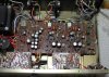
ps I attached a 'before' pic to give a view of the insides. I realize that the offset and bias trimpots are reversed in the service manual.
I've spent many hours trying to debug this issue and I am almost ready to throw in the towel. I am generally a parts replacer but am eager to learn and have a good foundation of what the different components do individually and have learned general troubleshooting procedures but am not yet at the point where I can determine what is causing this issue.
I bought this amp knowing that there was a 'scratchy' channel. Lo and behold the deoxit was not the solution - I should be so lucky.
Anyhow, here is the schematic for those interested in helping me out:
https://home.comcast.net/~devanymarino/LUXMAN_L80_L80V.pdf
Symptom: Right channel sounds like crap (very distorted - see image). The left channel sounds wonderful.
Here is what I know:
1. When injecting a 1khz sine wave in the AUX input the output waves looks beautiful through the preamp and tone controls. I checked this by hooking my scope up to pin 1 (which I believe is the input from the pre to power amp - there are no jumpers on this integrated).
2. The output of the left channel wave is beautiful (see photo)
3. The output of the right channel is very distorted (missing peaks)
4. The DC offset of both channels has been dialed down to zero in both channels
5. The voltage taken from the collector of all four output transistors is a solid +/- 46V
Based on what I know of things I figure there is an issue supplying + voltage to some part of the right channel driver board. I am assuming this because the top half of the peaks is missing. This service manual sucks.
Here is what I have done so far trying to fix this issue:
1. Replaced every electrolytic capacitor in the unit (even the ripple filters - there is no AC ripple)
2. Replaced every transistor in the problem (right) channel (even outputs)
3. Replaced the relay and protection circuit transistors
4. Resoldered the joints
5. Replaced both multijunction diodes in the right channel
6. Tested the values of many (but not all) resistors between right and left channels (lifted legs, cannot find discrepancies)
If anyone can tell me a good next step that would me amazing of you.
Thanks!
Rob
ps I attached a 'before' pic to give a view of the insides. I realize that the offset and bias trimpots are reversed in the service manual.
Attachments
Last edited: