• The move to the new server is done. There are some software and database maintenance updates in process. This has us passing the hat around to help out. We appreciate any donations. Seriously, even a dollar helps. The payment page may be found here - https://www.audiokarma.org/support.html

Loudness not deap on au217

Ian DEVERELL

New Member
Hello all. I have recently aquired an interest in restoring vintage amplifiers. The first two are both AU217's I am no expert but with the help of all you expirienced people I managed to fix the first one that basically had a problem with the two pairs of transistors on the phono board. Then I got on to the second one.
Initially it had a problem that seemed to be coming the volume potentiometre. At various volumes the left channel was coming and going . I tried cleaning the potentiometre with contact cleaner but wasn't able to fix it. So I replaced it with an ALPS which was electronically the same but physically different. Im not realy satisfied with that as instead of being soldered to the board I have had to use wires. Anyway after doing that the baby sounded good but only after a few minutes warm up. So with the help of https://audiokarma.org/forums/index.php?threads/sansui-au-217-restoration.755714/ I changed all the electrolyte capacitors except the two big ones.
Now it sounds pretty good and in some ways even better in the mid ranges than the first one. But for one problem.
When I put the loudness on with the treble and base in the middle it sounds horrible!
The treble goes up but not the base.
Any ideas why?
 
Register to hide this ad
Sounds like you need to clean the treble and bass pots. Or the loudness switch. What happens when you turn the knobs?
 
Hello. Thanks for the quick reply. I find the treble and base varie more than on the first machine. That is to say it makes more of a difference. However in the neutral position the sound is too high for my liking. I get a reasonable sound when I crank the base two notches to the right.
 
Your replacement potentiometer may be the reason for this. The loudness control relies on a derivation of the potentiometer near 50% of the way up, to gradually dissengage the lodness effect as you increase the volume. Depending on the curve of resistance versus rotation the loudness controll may be more excessive with the new potentiometer. The volume potentiometers are logaritmic so a linear potenciometer will behave differently. What model is the new Alps potentiometer?. Do you have a picture of the back side of it to see it?
 
Hello and thanks,
I have a feeling you might be right. I have looked on the famous auction site where I bought it and this is how it is described:
Potentiomètre 250K Log ALPS Audio AMP Contrôle Volume Pot Stéréo W Contour M

So the log is ok but what is w Contour M? I see that others are labeled as "with loudness". Stupidly I presumed these ones had a push pull loudness switch.
The photo on the site is not good enough to see the writing on the back so I will have to get the card out again this weekend to take a photo unless of course the discription is enough?


Environ
 
Hmmm.. I am not sure. I saw an auction potentiometer Alps 250K with exactly that description. Judging by what I knew about the RK27 Alps the lettering on the label indicates that is not authentic Alps (they always have serif in the word ALPS). Please, don’t get upset by what I am saying. This does not mean that the part you purchased would not be a good potentiometer. I have some fake Alps parts which are decent. If I remember correctly, the AU-217 does not use the square case Alps black beauty or blue velvet type. It uses a potentiometer which comes in a round metal enclosure.

If your part turns out to be unsuitable you may be able to use the Alpha brand potentiometer (excellent quality) or the 16 mm version of the Taiwan Alpha brand (readily available and acceptable quality).

My concern in my previous post is the dependence of the resistance with the rotation angle.

This website, and this other website have some useful information regarding the type of "taper curve". I don’t know what they mean by "M contour". I know that the Alps MN curve potentiometers are for balance. Unfortunately different brands may use a different notation. What I would do in your situation is to install a knob and use an improvised scale drawn on a piece of cardboard with markings made every 20 degree using a protractor, and then mount the original potentiometer on this cardboard scale with the knob and measure the resistance using a DMM. The plot of R versus angle will be elucidating. Please share it here if you measure it.

EDIT:
The Au-217 schematic specifies a 250K (B) type (Contrary to what said in my previous post) According to this site, B stands for Linear dependence of the resistance with rotation (which is unusual. It would be best if you can measure the resistance of the original potentiometer to see at least approximately if the resistance increases linearly or not with the rotation.
 
Thankyou again.
In the meantime I have been doing a bit o research myself.
According to the manuel the original potentiometre is an A type which if Understand corectlty it being of Japanese manufacturer it is logarithmic. However the actual one I took out has 250KoBX2 stamped on it. It does have an A in the middle of a circle stamped as well.
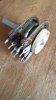
View attachment 1826736 View attachment 1826740 View attachment 1826736 View attachment 1826740 View attachment 1826743
When I bought it there were signs that it had already been removed so I I presumed somone had tried to remove it and fix it. But maybe it was changed? So I guess doing your test is a good idea.
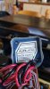
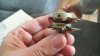
I also think the one I bought is a fake. View attachment 1826736
 

Attachments

  • 20200411_164900.jpg
    20200411_164900.jpg
    61.9 KB · Views: 31
  • 20200411_132158.jpg
    20200411_132158.jpg
    83 KB · Views: 32
  • 20200411_164937.jpg
    20200411_164937.jpg
    56.2 KB · Views: 32
  • 20200411_164924.jpg
    20200411_164924.jpg
    55.3 KB · Views: 30
Sorry, my mistake. In the circuit diagram that I have for the AU-217 it says 250K (B), but I do not have the full manual. You are correct the parts list calls for a logarithmic type which makes more sense.
I agree that the one you bought looks like the copy. Nevertheless, not a bad copy. The original one does not look terrible. Checking the potentiometer you have may help you determine if it is really bad or if you can repair it and reinstall it. It may be possible to completely dissasemble it clean it, insect the integrity of the carbon track and rebuild it. Also, you may compare the one you purchased if you measure that one also. My suspicion is that in the lower part of the resistance curve (from zero up to the derivation for loudness) there will be different. If they match reasonably well, then that means that the issue with loudness that you mentioned is not due to the potentiometer.
 
Ok then. I have been comparing the two and am convinced that they are not the same. If I label the pins from 1 to 4, 4 being the extra one.
They both are about right as standard pots.
270k for the old one on the channel that works and 266k for the new one. My multimetre might not be accurate.
On the old one here are the readings with volume right down.

Pin 4 pin 1 143k
Pin 4 pin 2 143k
Pin 4 pin 3 126k
With volume right up
Pin 4 pin 1 143k
Pin 4 pin 2 126k
Pin 4 pin 3 126k


And for the new one volume right down
Pin 4 pin 1 27k
Pin 4 pin 2 27k
Pin 4 pin 3 238k
With volume right up
Pin 4 pin 1 27k
Pin 4 pin 2 238k
Pin 4 pin 3 238k

Conclusion the new one is not compatible.

I did start to try and get the old one apart but gave up pretty quickly. I have also seen a sugestion on a french site which basically says the loudness resistance is about 1/2 the full resistance so use a resistor instead.

Even if you don't speek French the diagrams should make sense.https://www.astuces-pratiques.fr/electronique/potentiometre-a-4-broches-remplacement

Not realy convinced that this is the perfect solution but maybe?
 
There is the problem. The location of the derivation in the original potentiometer, is at 143 K Ohms from the zero volume point while the new potentiometer the location of the derivation is at 27K only. This means that the loudness will drop out of your circuit at very low volume. Too bad!.

I visited that link. That solution resricts the maximum volume that you are going to get. There are not 125K potentiometers available, so you may go with a 100K potentiometer and then add a 150K resistor to get the desired 250K resistance. But the variable part of the potentiometer is less than 50% of the original range, so your maximum volume will be restristed to the point at 100K. Also the loudness will be active in the whole volume range since the derivation will be at 100K. In my opinion, not a good solution. You can give it a try if you want. I know it sounds challenging, but trying your best to rescue the original potentiometer may be the best solution. There are members in this forum that have dissasebled the volume potentiometer to clean them. I think you may be able to do this if you take your time.

Edit:

Did you see this:
https://www.sansui-vintage.com/product_info.php?products_id=329&osCsid=6ku7pp58mdumdj964vkom1mr83

And how about this:

https://www.sansui-parts-shop.com/index.php?page=details&prod=2677&cat=335&group=28

These are in europe, and you may be able to get a better deal.

Good luck
 
Last edited:
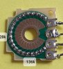
So I opened up the new one. That was easy enough. What I found was that the loudness tapped into the physical middle (1 on my photo) rather than the logarithmic middle (about 2 on my photo) An expert solderer with the right equipment could probably modify it but for the moment I think I will leave that option.
If I type 250k potentiometre loudness in Ebay it comes up with all sorts of variants from various, mainly Chinese websites but no datasheets. So I expect that the best option is getting the old one to work. I did find a second hand one on the web but at €30 I thought it was a bit steep.

20200412_122131.jpg 20200412_115942.jpg 20200412_120136.jpg I just realised that you had posted a couple of links to used parts too. One of them is the one I referred to. The other one doesn't have the 4th pin in the same place so the other pins may not adapt either. Could be a solution if all else fails.
My first erreur in taking the original pot appart was trying to get the front one apart . Now I have the cover off the back one I am meditating how to leaver the next bit out withot breaking anything.
 
Just in case anyone was wondering, I was usable to fix the original pot. I couldn't get it appart. Hoever I did find a work around using the new pot which only half satisfies me. I scraped the printed circuit at the 136k mark (the outside bit that goes up to the middle) then I put a blob of solder to connect it over to the middle. Of course I did the two chanels. It did the job but is still not the perfect solution it is less original Sansui but also because it is not connected directly to the circuit board and there isn't much room to get some good insulation in betwean the connections and the board. I did take some photos which I will try and find if anyone expresses any interest.
 
Back
Top Bottom