• The move to the new server is done. There are some software and database maintenance updates in process. This has us passing the hat around to help out. We appreciate any donations. Seriously, even a dollar helps. The payment page may be found here - https://www.audiokarma.org/support.html

Lux OY15-5 OPT rewind

familyguy

Member
Preparing to rewind an OPT from a Lux amp, the OPT is a model OY15-5 15W 5K, in general Lux OPT's seem to be highly regarded, so will be interesting to see what sort of magic is in the windings/layout.

A bit of background:- A local amp builder for whom I wind transformers handed me a home made bobbin which looked to suit a 50mm stack of EI76 laminations, the instructions were for me to calculate turns and wire size using his winding layout, once he was ok with the design then to go ahead and complete the winding, a few text messages later I find out the resulting transformer is to replace a failed Lux OY15-5 OPT, an attempt had been made by a 3rd person (unknown) to unwind the transformer and document the winding layout, turns etc for later rewinding, the 3rd person had given up saying too hard, so it was decided to wind a new transformer using the old laminations, which is where I entered the picture.
I believe that model transformer was common to a few different Luxman amps - Luxman amps have a good reputation and and bring good money so I figured it was well worth the effort the rewind the transformer correctly, he gave me the damaged windings to see if I could do any better unwinding the transformer, document the winding layout and then rewind. While I don't have the original laminations at this point, an EI76 lamination fits the bobbin - 25.4mm central leg - so I assumed this was the correct size.

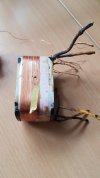
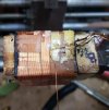
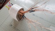
The OY15-5 transformer is potted in pitch and luckily (for me) someone had already done this part, and removed the transformer proper from its enclosure and also melted off most of the pitch, they had also removed some of the windings. On examination, it looked to me that there were 3 secondary windings all connected in parallel and possibly 4 primary windings with ultralinear taps. As given to me a primary winding was exposed - inserting an EI76 lamination showed a fair amount of room between the winding and the lamination, this supports the story that one or more windings - primary or secondary - had already been taken off, working on the assumption that the last winding would have been a primary I guessed that a primary and secondary winding had already been removed, if this was correct then primary windings would 5 with 4 secondary windings
20241228_090159.jpg20241228_090212.jpg
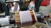
On to the unwinding - the winding (primary) came off easily I noted that no special precautions had been taken to anchor the last turn, just 1 narrow strip of mylar tape the hold it. The primary layers were separated by a layer of thin plastic like insulation definately not paper - possibly mylar or maybe even nylon around 0.04 - .05mm thick, it feels more like nylon to me.


Next came 1 layer of transformer paper insulation 0.15mm thick covering the secondary winding which consisted of 2 layers, 1 full layer and a second layer with various taps to cater for different speaker loads. Under this was another layer of transformer paper to separate the secondary from the primary layer underneath - it is here I've hit an first obstacle
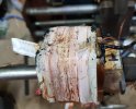
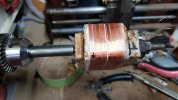
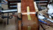
this primary winding is completely fused together with the thin interlayer plastic insulation - some sort of massive overload has heated it to the point where the plastic insulation has melted and fused to the wire, it's going to need some extra care to unwind so I can count the turns, tried to carefully unwind but the thin 0.19 primary wire breaks easily, I'll need to find a way to soften the fused mass so I can unwind.
20250109_143647.jpg
20241230_121422.jpg
20241230_202149.jpg
20241231_114834 1.jpg

So looks like I'm going to need some patience here getting the wire off this winding isn't going to that easy.
 
Register to hide this ad
Any idea what model amp that was used in? Might give a clue about what the secondaries did. Only Lux amp I've ever had my hands in had a couple of cathode feedback windings.
 
Wow. I am impressed.

You like challenges.

In the first pictures, the OT leads are not marked: how are you going to know how windings are interconnected?
 
Not sure which amp they are from or even if they were in a Lux amp, I may be wrong but my belief is that Lux sold a range of amp parts called Lux-kit, so one could purchase just the output transformers for an amp build.
The plate on the base of the case only shows P1, P2 - Plate connections, SG1, SG2 - Ultralinear screen grid connections, and B1,B2 - HT or B+ connection, so I'm quite certain there are no cathode feedback windings.

I'm not overly concerned about the leads/connections I know it is meant to be 5K primary, secondary speaker taps are 16, 10, 8, 6 and 4 - so once I have the turns count for each of the primary windings it shouldn't be too hard to work out the connections/leads
 
The Lux O/P transformer would have used NEC High B laminations which were an improvement over grain oriented steel.
 
They used them on both Thier Luxman range, and Luxkit range, and they were also sold separately. The A3500 I have on they way uses a pair of 5k's I believe.
 
I've hit a snag with the unwinding of the Lux output transformer - one of the primary windings looks as if it had been covered by a layer of thin plastic insulation (mylar/nylon ?) this insulation covering had well and truly melted fusing all of the wires together along with the plastic insulation layer - I spent the best part of an hour trying various methods to free the wire from the melted plastic, none of the solvents I had worked (MEK, acetone, THF, xylene), a small chef's type blow torch only melted the wire, and my hot air rework tool did melt the free ends of the plastic insulation but did nothing to the bulky mass in the middle, I'd unwind 1/2 turn and the wire would break rather than continue I decided to cut the complete winding through with a stanley knife and take it off in one piece, the idea being that once off in one piece I could then count layers and work out the turns count for that primary winding. This also proved to be harder than it sounds, the thin plastic insulation crumbled at the edges and the middle was just a complete solid mass - I wasn't 100% certain if it was 4 or 5 layers, I left it for later knowing it would be a long slow process if I had to separate each wire for counting.

20250108_230041.jpg20250108_195728.jpg

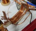
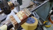
The rest of the unwinding was without issues - the secondaries were easy to count and workout the winding sequence - if my initial assumptions were correct then the transformer had 4 secondary windings in total, all connected in parallel, wire thickness 0.4mm - 2 layers in each secondary, 75T each layer, connected in series for 150T total - one full layer and the other layer with taps taken off to cater for 5 different speaker impedances - I believe the speaker impedances are 4,6,8,10 and 16 ohms. As with the primary no special precautions for anchoring wires, just a narrow strip of tape (looks like mylar) and a narrow strip of transformer paper to insulate where the secondary taps were taken across to the outside of the bobbin for termination.

20250109_150224.jpg20250109_143159.jpg

The last layer of some of the primary windings did not take up the full width of the winding former, some of the primary layers were quite unevenly wound almost as if they had been the wire had been guided across the winding former by hand rather than with a machine. The turns count on the individual primary layers was inconsistent the count varied from 130turns per layer up to 150turns per layer - most were in the 130-140 turns perlayer range, the winding former is this another indicator that perhaps the transformer was wound by hand, allowing for a 3mm margin 160 close wound turns is a comfortable fit

20250109_142224.jpg

With all of the windings removed from the former the one primary winding that was melted together still needed to be dealt with to determine the number of turns in that winding, the edge insulation that had not been fused to the wires just crumbled when I tried to count the layers, I counted the layers as best I could and came up with 577 turns but decided to do it correctly so for the next day or so I'll sit at the bench under a magnifier and with a solder rework heat gun I can heat the wires one by one and pull them from the mass.
 
https://audio-database.com/LUXMAN/kit/a3500.html shows the transformer on the scat but no voltages. Don't know if that helps at all.

This schematic is more complete with some numbers. https://www.audioservicemanuals.com/l/luxman/luxman-a/a-3500/2352899-luxman-a-3500-schematic.

But it seems you have gotten some good info on the UK VR site with a link to the transformers in an SQ38FD.

Anything that gets the transformer rebuilt will be nice to know. Luxman isn't making them anymore and saving some of their gear is a worthy cause.
 
Last edited:
Very interesting work you are doing here. It is true dedication taking on a tear down like this. I’ve never had a Luxman amp on my bench or even heard one. I understand they are quite nice in build and sound quality. Best of luck with the rewind!
 
It took a while but by heating each wire with my hot air rework tool I managed to extract each turn one wire at a time from the fused mass, sorted them into bundles of ten and came up 725 turns - looks like my estimate of 577 was bit off the mark.

Screenshot 2025-02-05 233148.jpg

With all of the windings removed and counted as best I could this is the winding sequence going from the top outer winding down to the first winding closest to the core

Pimary - unknown number of turns, this winding had been removed by a 3rd person. #1
Secondary - 150 turns
Pimary - 467 turns #2
Secondary - 150 turns
Pimary - 725 turns #3
Secondary - 150 turns
Pimary - 776 turns #4
Secondary - 150 turns
Pimary - 263 turns #5

It was all starting to come together, but I still had an unknown primary winding removed off by a previous 3rd person, I contacted the amp maker for some more info and it turns out he is the mystery 3rd person that attempted to unwind and document the winding layout, saying he had removed 2 windings (1 primary & 1 secondary) and that the top primary winding (first one removed) was only a 2 layers, my notes told me that the primary winding closest to the core was only 2 layers for 263 turns so I'm assuming top and bottom primary windings are the same at 260 turns each - he also added that on testing the one good OY15-5 transformer he has, the primary impedance is closer to 4K than to 5K, he also gave me the metal enclosure as well as the laminations - turns out the laminations size is EI78 not EI76 as I initially assumed - EI78 central leg width is 26mm against EI76 25.4mm while this amounts to almost nothing as far as the cross section of the core goes the EI78 lamination has a 1mm deeper winding window, which can make a big difference when it comes to fitting the windings in.

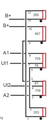
With a primary impedance of 5K and 150 turns for a 16ohm secondary, the primary would need to be around to 2650 turns total, or 1325 turns each side of the centre tap. Looking at the turns count of the individual primary windings, windings #2 and #4 wired in series would be, 776+467 = 1243 turns, one could assume these 2 windings formed one half of the primary, that leaves 725+263 plus 260 turns from the unknown primary, assuming it was 260 turns that would make the other half of the primary 725+263+260 = 1248 turns - the two together give 2491 total primary turns - it all seems to fit quite well. Turns ratio for a 16ohm speaker load is 2491/150 which works out to be 4.4K primary, this more or less agrees with the info I had from the amp maker regarding the primary impedance. Referring to my notes on the location of the ultalinear taps I worked out a connection diagram for the various primary windings, the secondary isn't shown as it is straight forward,4 windings connected in parallel -

Screenshot 2025-02-09 101613.jpg

What was special about windings ? I can't really that there is anything, apart from possibly some special grade of laminations, 5 primary and 4 secondary is not unusual for a high end transformer - all of the primary layers were separated by a layer of thin plastic - not paper - insulation approx 0.05mm thick - could be mylar or nylon, all of the secondary layers were separated by a layer of transformer paper 0.16mm thick and all windings primary and secondary were separated from each other by a layer of transformer paper 0.16mm thick, no special precautions were taken to anchor the primary or secondary leadout wires, just a simple piece of narrow mylar tape to hold the wire down, all of the taps for ultralinear were simply soldered on in the middle of the layer with transformer paper to insulate from the winding, similarly secondary taps for speakers were taken out to the side over a narrow piece of transformer paper to insulate, given that the transformer is potted in pitch no special precautions need to be taken as once the transformer is potted into it's enclosure there is no strain on the wires. The wires that join the various primary windings had no insulation sleeving and all connections between the various primary windings were done within the transformer windings. Wire sizes measured are 0.19mm primary and 0.4mm secondary, this is with the insulation varnish, I burnt off the varnish with a cig lighter and measured wire sizes were 0.18mm and 0.38mm. Just about all of the rewinds I've done have had the primary split up into a number of windings with an equal number of turns in each - this has some windings with odd turns counts - I guessing this was done to balance the DC resistance of each primary half, it's quite common to find output transformers where the DC resistance of the primary halves differs.

Once the unwind process was finished I did some serious internet searching and eventually came across this Japanese blog https://musenan.blogspot.com/
Even though Google did a reasonable job of the translation, some info was simply lost in translation, I was though able to work out that my assumptions about the unknown primary winding were correct and also that I had the connections between the windings correct.

Now that I'm happy with the info on the wire sizes, turns count and winding layout I can proceed with the actual rewind, I'll need to plan this carefully, the secondary windings would I feel present the biggest challenge for me - 4 windings in parallel - each winding consists of 2 layers - one full layer of 75turns and a second layer with taps for 4,6,8,10 and 16 ohms - the 4,6,8 and 10 ohm taps each have 2 wire bought to the outside, one wire out and one wire in - making 8 wires bought to the outside - add the common and 16 ohm taps brings the total to 10 wires for each secondary winding. As there are 4 secondaries the total number of secondary wires to keep tabs on is 40.
 
The complete primary as can be seen from the winding diagram consists of 5 separate windings - there are 3 links that join the appropriate windings together and 6 external leads that are the connections for the anodes, B+ and G2/ultralinear taps.

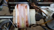
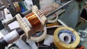
To aid in the winding process I drew up diagrams of the wind sequence for both primary and secondary. The original former was in good order so I elected to re-use, I also spent some time making a mandrel to hold the former on the winding spindle, the mandrel needs to run true so the windings aren't skewed on the former, the mandrel had a 'cheek' on the RH side, I cut slots in this to keep the various primary windings in the correct position, so I wouldn't need to have cross them over one another when the final winding connections were made - I planned to just eyeball the secondary lead-out wires as I went.

20250122_141024.jpg

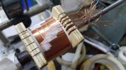
The actual wind started badly, the first primary winding of 2 layers was just routine, I used the slots I had cut to position the leads, it worked ok - but when it came to the secondary, eyeballing it was harder than I thought it would be, the winding former is only 27mm or so wide - with the secondary, which as previously mentioned this secondary has 6 taps and a total of 10 wires bought out to the side, I found it difficult to maintain an even spacing between all of the secondary taps, I could see this getting out of hand as each secondary winding was added so I decided that what I needed was a 'cheek' piece with slots on the LH side to maintain an even spacing between the taps - better to start again so I striped off the just completed secondary layer and modified the mandrel by making an end cheek from plywood this had 6 even spaced slots for the secondary.

20250118_164002.jpg
20250124_110338 1.jpg
20250125_140019 1.jpg


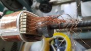
Back at the winder I started on the first secondary winding - the first layer has all of the taps, I have to say they are not the easiest thing to do - it's quite hot here this time of the year (over 35C in the workshop) and I found that the mylar tape I was using liked the heat even less than I do, it tended to let go the turns that were being held down resulting a real mess, possibly the heat softened the adhesive, a lot of patience was needed. As with all things it gets easier each time you do it, so by the time I reached the last secondary winding I had a system that more or less worked, I was quite relieved that part was over, the last primary winding went on easily - major part of the rewind done, next step is load the laminations and run an ac voltage into the primary so I can measure and test the voltage at all of the secondary taps, it's then easy to calc the primary impedance for all speaker taps, should be close to 4.4K - while the transformer is marked as 5K, I've found it's not at all unusual to find this sort of discrepancy in older transformers

20250127_154930 1.jpg
 
Great looking work! I have a question - when building a transformer, do you make an effort to account for winding resistance in stating the impedance specification, or do you use only the turns ratio? The reason I'm asking is that the term "impedance" by definition is the sum of resistance and reactance. This has been an issue of continuing discussion here on AK, particularly because it results in inconsistency when measuring an output transformer. Due to DCR, a measurement made with a load on the windings will produce a different result than one made with the transformer unloaded. The difference usually isn't insignificant.

Jack
 
I believe the DC resistance is not taken into account when calculating the turns/impedance of an output transformer - in rewinding transformers I've found that there can be discrepancies between either the marked impedance or that shown on the schematic, I put this down to the way transformers of this vintage are wound ie not on a bobbin but on a square/rectangular winding former or tube.
Once the designer settles on the turns count and wire size they need to take into account that each layer of a winding should take up the full winding width of the former, this keeps each layer flat ready for the next layer, if each layer isn't flat the wire can fall off the edges. For this reason the designer should keep the winding layout as full layers of both primary and secondary - however this might be at odds with the intended turns count - the final impedance of the primary is not that critical, as the speaker impedance is not constant across the audio range so if the impedance comes in close enough then all well and good, if not the designer might need to juggle wires sizes and turns to maintain full width layers and still achieve an acceptable primary impedance.

That's my take on it after rewinding transformers that are wound on a former or tube, I can't recall ever having found a discrepancy on newer transformers that are wound on a proper bobbin with side cheeks, I've done quite a few Drake and Dagnal guitar amp transformers and the impedance ratio as calculated from the turn count is almost dead on.
 
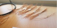
To run a voltage test with the transformer I need to make temporary interconnects between the relevant primary windings and also sort the secondary taps into their groups - ie 16 ohms, 10 ohms etc - starting with the secondary- each secondary winding (there are 4 total) should have 1 lead each for the 16 ohm and 0 ohm common taps - all of the others should have 2 leads each making 10 in total, as there are 4 windings I should have 40 leads in total. I started counting - only 38 leads - I checked and rechecked - only 38 leads. On closer examination under my bench magnifier I could see that I had missed one complete layer of 75 turns, it turned out to be the very first secondary winding, to rectify this correctly meant stripping off everything I had done - if I could have kicked myself in the backside I would have done it.

The transformer would still have functioned without this winding but the current carrying capacity of the secondary would have been reduced with one less winding in parallel. In theory I could just wind one extra layer of 75 turns on top and as long it was connected correctly it should still work the same - but the object of the exercise is to rewind as it once was, there was no option but to re-do it - the upside - if you can call it that - is that having done it once the second time should be easier.

Screenshot 2025-02-10 002312.jpg
20250203_141626.jpg
20250204_112357.jpg

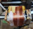
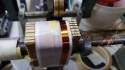
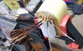
As can be seen in my previous post the first plywood end 'cheek' I made was bit on the small side, I hadn't given any thought to the windings growing in size as each layer was added, once the windings had grown in size the wire didn't want to stay in the slots, so I made 2 new end 'cheeks', larger than the first ones this can be seen in the photos. Partway through the wind I hit upon another idea to anchor and keep in place the secondary winding speaker taps, this seemed to work quite well and the job progressed at a better pace, I was happy when finally finished.
Once the windings were all done I dribbled varnish in between the layers first one side and then the other to stabilise the windings - slipped different colour sleeving over the primary wires to identify them, double checked the secondary leads were all there and then set about stripping the varnish from the ends of 40 secondary leadout wires - something I'm not fond of at the best of times. The original EI78 lams were still in need of a clean so I used some EI76 lams loaded into the windings to test that I had everything right, the primary impedance across all of the 6 speaker taps worked out at 4.4K or very close to so it was ok to make the connections between the variuous primary windings permanent.

20250206_122347.jpg
 
If the customer is satisfied with the end result then all will be good.
Much more patience than I would have.
 
Back
Top Bottom