• The move to the new server is done. There are some software and database maintenance updates in process. This has us passing the hat around to help out. We appreciate any donations. Seriously, even a dollar helps. The payment page may be found here - https://www.audiokarma.org/support.html

Luxman L-100 Fuse Wiring Issue

GabrielS

Active Member
Hello to all, I've some broken wires interconnecting the fuses located behind the transformer. I'm hoping someone can post a closeup photo of the area and how the wires are attached so I can confidently reconnect them. The fuse array is mounted from the bottom panel with only the holder connections visible from the top, the design must be from an earlier version of the L-100U amp. Thank you for your help!
 
Last edited:
Register to hide this ad
Service manual is probably out of date, it shows 2x5AT speaker protect fuses(PB-647) and 1x5AT on neutral on transformer primary.
 

Attachments

  • L100_fuses.png
    L100_fuses.png
    34.3 KB · Views: 7
Thank you for that image. Unfortunately, my fuse array is mounted from the bottom panel with only the holder connections visible from the top, the design must be from an earlier version of the L-100U amp.View attachment 3839868
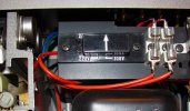
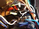
Below is a closeup of the area in question which is located behind the transformer. The black lead with the green tape has one end attached to the 5 amp input fuse while the other side broke off from somewhere. The two fuse holders on the left are for left and right channels while the one on the right is for the ac input. Above the fuse holders are two ac jacks with, each having a brown capacitor. There are a couple possibilities where the broken wire goes but it's not clear were exactly and don't want to risk damage connecting to the wrong lug.
 

Attachments

  • Broken black lead from 5amp fuse for ac input.jpg
    Broken black lead from 5amp fuse for ac input.jpg
    141.7 KB · Views: 23
Yeah it goes to the AC socket (Unswitched outlet)

Looking at where the power cord enters, what are the colours of the 2 cables ? Brown(A), Blue(N)?
The black wires confuse me, also the 2 caps
 
Yeah it goes to the AC socket (Unswitched outlet)

Looking at where the power cord enters, what are the colours of the 2 cables ? Brown(A), Blue(N)?
The black wires confuse me, also the 2 caps
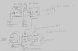
Thank you for your reply. Yes, it is confusing even when looking closely with a magnifying glass. The ac cables coming into the unit are black & white. black connecting to one side of the ac unswitched receptable with the white going its other side. I drew a layout hoping to clarify as the service manual does not show exactly how connections are done.
 

Attachments

  • luxman_l-100 Fuse Connections.jpg
    luxman_l-100 Fuse Connections.jpg
    43.4 KB · Views: 13
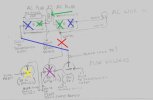
There is an error in your sketch, the white wire from AC line to right speaker fuse, see red cross.
If this is true then you would be sending mains AC to the speaker fuse and then onto the speakers.
That white wire should be going to the power switch. Try the following,

- unit unplugged from mains
- L-100 power switch set to ON
- Measure resistance between green crosses, ie, Unswitched socket, white wire and
Switched socket black wire from power switch, ideally less than 1 ohm, ok if a few ohms.
- Set L-100 power switch to OFF
- Repeat resistance measurements between green crosses, expect OL. Reading will ramp up from
a small value to kohms and beyond and the MM current charges up cap (green)

For my own thinking, I'm calling the black wire from the AC cable the Neutral and the white wire
the Active. Yeah I know you guys continue to use non-polarized AC plug in some places.

So the white wire/Active is switched
And the Black neutral goes to the fuse (as per schematic)

The broken black wire should connect to the Neutral black wire at either the switched or unswitched
sockets, see blue crosses. I've shown a blue line where I think it should be connected.

The Black wire "to transformer input" looks wrong.
The transformer inputs are the
- Active, ie, white wire to power switch, other side of power switch to transformer input
- Neutral, blue wire other side of fuse.

The wiring does not conform to any standard, looks like a hatchet job. The Black wire to power
switch is bad as is the use of white wires "everywhere"

The speaker fuses also look like a mess, the wires should go to the speaker selector switch not
power switch. Try the following,
- L-100 powered off/unplugged
- select speaker System A and B (if possible to do both)
- measure resistance between left speaker fuse (yellow cross) and left speaker connector/post
either system A or B, ideally zero ohms, ok if less than 5ohms.
- repeat for right speaker fuse (purple cross) and right speaker post

 

Attachments

  • L100_sketch.jpg
    L100_sketch.jpg
    52.4 KB · Views: 10
Yeah, looks to me like someone has been in there previously. Pretty unusual that those wires would just break.

Looks like the switch(?) in the upper left corner of the picture in post #5 might not be quite right either; like it's coming apart.

What's the back story on this situation?
 
Last edited:
There is an error in your sketch, the white wire from AC line to right speaker fuse, see red cross.
If this is true then you would be sending mains AC to the speaker fuse and then onto the speakers.
That white wire should be going to the power switch. Try the following,

- unit unplugged from mains
- L-100 power switch set to ON
- Measure resistance between green crosses, ie, Unswitched socket, white wire and
Switched socket black wire from power switch, ideally less than 1 ohm, ok if a few ohms.
- Set L-100 power switch to OFF
- Repeat resistance measurements between green crosses, expect OL. Reading will ramp up from
a small value to kohms and beyond and the MM current charges up cap (green)

For my own thinking, I'm calling the black wire from the AC cable the Neutral and the white wire
the Active. Yeah I know you guys continue to use non-polarized AC plug in some places.

So the white wire/Active is switched
And the Black neutral goes to the fuse (as per schematic)

The broken black wire should connect to the Neutral black wire at either the switched or unswitched
sockets, see blue crosses. I've shown a blue line where I think it should be connected.

The Black wire "to transformer input" looks wrong.
The transformer inputs are the
- Active, ie, white wire to power switch, other side of power switch to transformer input
- Neutral, blue wire other side of fuse.

The wiring does not conform to any standard, looks like a hatchet job. The Black wire to power
switch is bad as is the use of white wires "everywhere"

The speaker fuses also look like a mess, the wires should go to the speaker selector switch not
power switch. Try the following,
- L-100 powered off/unplugged
- select speaker System A and B (if possible to do both)
- measure resistance between left speaker fuse (yellow cross) and left speaker connector/post
either system A or B, ideally zero ohms, ok if less than 5ohms.
- repeat for right speaker fuse (purple cross) and right speaker post
Many thanks for your input and corrections. This is the way I received the unit and have been struggling in getting it operational. No wonder the seller gave up on it and sold it for the low price he did. As I was going through the circuit boards, there were some issues found especially with the soldering and inconsistencies of parts positioned on the circuit boards compared to how the schematic shows them.
 
Yeah, looks to me like someone has been in there previously. Pretty unusual that those wires would just break.

Looks like the switch(?) in the upper left corner of the picture in post #5 might not be quite right either; like it's coming apart.

What's the back story on this situation?
The switch in #5 is the on/off for the touch mute function. This unit was an eBay purchase a number of years ago that was stuck in the protection mode. I've been recently attempting to get it working but dealing with obstacles along the way such as sketchy soldering joints and wire placements. The wiring connections are easily broken so moving the boards has been a very careful process.
 
I've just read that the "standard" USA wiring of your 3 pin plugs is Black=hot/active, White=Neutral so I was wrong complaining about the overuse of these colours. Your wiring is the opposite with some errors thrown in.
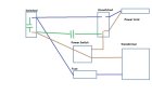
Suggest rewire this area to comply with service manual, probably take 1-2hours depending on access. I will make up a sketch.
 
IMO this is what it should look like, I've used AU codes, you would replace blue with white and brown with black.
Starting point would be carefully check what wires are going into the transformer and also power switch (in/out)
 

Attachments

  • RewireL100.jpg
    RewireL100.jpg
    36.4 KB · Views: 6
IMO this is what it should look like, I've used AU codes, you would replace blue with white and brown with black.
Starting point would be carefully check what wires are going into the transformer and also power switch (in/out)
Thank you for taking the time and preparing the illustration!
 
Back
Top Bottom