• The move to the new server is done. There are some software and database maintenance updates in process. This has us passing the hat around to help out. We appreciate any donations. Seriously, even a dollar helps. The payment page may be found here - https://www.audiokarma.org/support.html

Luxman L-100 help

quadmatrix82

AK Subscriber
Subscriber
Hi all I have been restoring a Luxman L-100 which wasn’t working after a recap and replacing zeners I have it up and running on one channel only, I’ve narrowed it down to a preamp fault the output modules work well on both channels when connected directly. Testing all the transistors appear ok on diode test and soldering looks good can’t see any other faults what else can I look for to trace down the left channel pre fault? Thanks!
 
Register to hide this ad
Was it working normal before the recap?
Exactly what is not working, eg, no audio on L/R(which channel?)
Assumed you've checked orientation of replaced parts (caps, diodes,,,). Also basic health check of power supply...
Do you have any test equipment (oscilloscope, audio probe...)
Will see if I can find the sm...
EDIT: Assume you are using AUX input to rule out phono stage...
 
Last edited:
Was it working normal before the recap?
Exactly what is not working, eg, no audio on L/R(which channel?)
Assumed you've checked orientation of replaced parts (caps, diodes,,,). Also basic health check of power supply...
Do you have any test equipment (oscilloscope, audio probe...)
Will see if I can find the sm...
EDIT: Assume you are using AUX input to rule out phono stage...
Hi mbz no it wasn’t working was stuck in protection lot of old leaky caps and zeners were toast…replaced the vd1221 diodes also as a precaution power supply tests good I have multimeter no scope and testing on aux
 
Was it working normal before the recap?
Exactly what is not working, eg, no audio on L/R(which channel?)
Assumed you've checked orientation of replaced parts (caps, diodes,,,). Also basic health check of power supply...
Do you have any test equipment (oscilloscope, audio probe...)
Will see if I can find the sm...
EDIT: Assume you are using AUX input to rule out phono stage...
Sorry will clarify left channel is distorted sounds like when a transistor is backwards but checked and can’t see that…
 
Again assuming you tested the PRE-OUTs/MAIN-IN to verify a preamp issue.
Switches can't be ruled out, suggest trying TUNER, AUX-1, AUX-2, same
problem on these inputs? For each preamp switch, put gentle pressure on
the switch so as to slightly shift the switch mechanism, repeat a few times
then fully depress/activate that switch, repeat a few times, note any change
good or bad. That switch probably needs further cleaning.

Have another look at solder joints in preamp, make sure all good.

Tracking down distortion without a scope is a bit tricky. You could build an
audio probe. Use an old RCA cable, connect a probe/bit of wire with a point, and
a series film cap for dc blocking 0.1-1uf/400-600V(?), connect RCA into AUX of
another amp for playback. Probably need a GND wire between amp under test and
playback amp. Or you could buy something like this,
https://www.ebay.com.au/itm/154045484576

It is certainly a toy but is useful for binary yes/no audio testing, it does
struggle with low level signals

 
Again assuming you tested the PRE-OUTs/MAIN-IN to verify a preamp issue.
Switches can't be ruled out, suggest trying TUNER, AUX-1, AUX-2, same
problem on these inputs? For each preamp switch, put gentle pressure on
the switch so as to slightly shift the switch mechanism, repeat a few times
then fully depress/activate that switch, repeat a few times, note any change
good or bad. That switch probably needs further cleaning.

Have another look at solder joints in preamp, make sure all good.

Tracking down distortion without a scope is a bit tricky. You could build an
audio probe. Use an old RCA cable, connect a probe/bit of wire with a point, and
a series film cap for dc blocking 0.1-1uf/400-600V(?), connect RCA into AUX of
another amp for playback. Probably need a GND wire between amp under test and
playback amp. Or you could buy something like this,
https://www.ebay.com.au/itm/154045484576

It is certainly a toy but is useful for binary yes/no audio testing, it does
struggle with low level signals

thanks mbz I did try via the main in/pre out to confirm the fault - switches have been cleaned but the left channel is weak and distorted. I tried on aux 2 and 1 it’s the same I’ll look at pb-636 and pb-640 again - I did see few broken tracks on pb-640 but they are repaired I’m assuming they ok continuity tested good
 
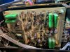
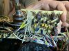
Few photos of eq and flat amp board
 

Attachments

  • 9EBEB1DC-8566-4B37-BDA1-BE35E7614DB6.jpeg
    9EBEB1DC-8566-4B37-BDA1-BE35E7614DB6.jpeg
    145.9 KB · Views: 45
  • 6E954DEA-D66D-4004-B419-0669CB5B5284.jpeg
    6E954DEA-D66D-4004-B419-0669CB5B5284.jpeg
    129.4 KB · Views: 45
  • AB3823C4-A84B-440C-9B6D-3E10F2947B99.jpeg
    AB3823C4-A84B-440C-9B6D-3E10F2947B99.jpeg
    143.9 KB · Views: 48
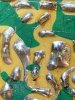
I would have expected wire wrap on those end pins, appears to be solder, though pic is not great. Original?
 
I would have expected wire wrap on those end pins, appears to be solder, though pic is not great. Original?
It’s factory as far as I’m aware I’ve seen other google pics that look the same I don’t see much worse wrapping in this model
 
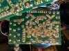
I’m looking at repaired track on q604b collector and emitter of q603a I scrapped to copper as previous repair with old transistors had broken traces I think the repairs are ok and there is continuity so I assume I can rule this out?
 

Attachments

  • B1A7FB36-B8ED-42F9-AD41-A3F11634287C.jpeg
    B1A7FB36-B8ED-42F9-AD41-A3F11634287C.jpeg
    148.1 KB · Views: 20
  • E4FBDF38-51BE-42CD-8F22-0CAFEB16D6DA.jpeg
    E4FBDF38-51BE-42CD-8F22-0CAFEB16D6DA.jpeg
    134 KB · Views: 19
  • Like
Reactions: mbz
I moved back to power supply to check over things today I noticed the below
R945 reads low circa 860ohm
R944 reads low circa 1.24k
R930 and r929 also read low 1 ohm the opposing channel reads much closer to the correct spec
Q913 reads lower on diode test to q910 - could these variances point to the preamp fault?
 
Parts list shows R944 4.7K and R945 as 1k while schematic shows R944 as 22k and R945 is not shown
however R943 is shown twice (47ohms and 330k). These parts are in the protection circuit (after
power amp stage) so difficult to see how they would cause a preamp issue. Also incircuit measurement
may give faulty readings. Resistors generally drift high and fail open rather than reduce in value.

Try building the audio probe. The idea is to test various points in the audio path, the probe
siphons off audio signal which is then played using another amp/speakers. The probe can be something
like a mini-grabber, a dc blocking cap is required then onto the playback amp. Use junk/disposable
speakers as you may get some dc leakage.

Trying to work out the L-100 audio path is probably beyond my pay grade, however other AK members
will know.
 
Back
Top Bottom