• The move to the new server is done. There are some software and database maintenance updates in process. This has us passing the hat around to help out. We appreciate any donations. Seriously, even a dollar helps. The payment page may be found here - https://www.audiokarma.org/support.html

Luxman L-30 idle adjust problem

JonyQuest

New Member
Hi there, been browsing threads on this forum the other day and saw a lot of enthusiasts for the Luxman L-30 and some pretty knowledgeable people here.

I'm a proud owner of the Luxman L-30 that i bought 10 years ago, this year it started failing on me though. Lots of distortion in the right channel, so did my research online and concluded my amplifier needed some well deserved new components. Ordered all the required items (followed Hilberinks site and a blog from Brahm, both were really helpful).

Anyway, replaced all the caps and transistors and started the baby up again for calibration. But got stuck there already pretty quickly, since when measuring for idle adjust I measure only 7.8mA over F203 and F204, so both channels (FYI turning the variable resistor does not do a thing).

Adding the fuses again I measure around -36.4V between F203/F204 and ground. Over P212 I measure -43.1V which seems a little too high.

I checked twice for wrongly installed transistors, but couldn't find anything yet. Maybe one of you have an idea on where to start looking next?

Edit: when I remove the fuse on 203 I measure -36.7V on the negative side and 8.21V on the positive side
 
Last edited:
Register to hide this ad
Hello. I too own an L-30, and I have had great help from this forum. I am newbie, but I have leaned a few things:
Make a Dim Bulb Tester, and use it whenever you have a faulty unit. It may save you a lot of collateral damage. If the bulb lights up, you have a short somewhere.
Forgive me for suggesting that you check orientation of all transistors again. Some newer substitutes have a different pin-layout than others (as you probably already know).
On (correctly oriented) transistors measure voltage on emitter and collector to ground in idling condition (DBT on, no input or speakers on and volume turned down to minimum). Be very careful not to shorten anything, e.g. by measuring on "neighboring" components.
Same voltage reading on emitter and collector indicates that the transistor is roast.

I have no experience with capping, so I do not know how a wrongly oriented cap affects the circuitry. Maybe some of the more experienced guys can contribute here, and correct me if my advises are not valid.

Good luck and have courage.
 
... Forgive me for suggesting that you check orientation of all transistors again. ...

Finally had time to look into it again, found the mistake this time! Had a datasheet which had a picture with orientation Emittor-Base-Collector (not the ECB like on the board). But after checking the datasheet again today I found an important detail: "Suffix "C" means center collector". Never trust pictures I guess...

Anyway, in the mean time I ordered a 10000uF 50v capacitor for the power supply, anyone that has a suggestion for a proper diode to replace the "HiFi Special" ones?
 
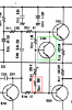
Since I was able to set the Idle adjust to 45mA (also did the zero DC offset calibration) on both channels I did some testing with some headphones. And things were up to a good start, things sounded lovely, until right channel dropped out and R215b was SMOKING!!!

Little heart attack! But that resistor is gone now, its in series with VR202b (the one used for idle adjust). Have not investigated further, probably have to replace that resistor first. But all seems weird, everything was sounding perfectly.
 
To my knowledge the problem is likely with one of the transistors, Q204 was the one I had the Collector-Base wrongly installed before. But I installed a fresh one, so either that one was already bad before installing, or something else happened.

Any tips?
 

Attachments

  • Screenshot 2020-01-05 at 21.33.42.png
    Screenshot 2020-01-05 at 21.33.42.png
    171.3 KB · Views: 12
Maybe take a look at Q203. Thinking need high voltage difference between Q205base and Q206base for R215 to smoke.
Any voltage measurements may help, like Q203,4,5,6 base to GND voltages.
 
Maybe take a look at Q203. Thinking need high voltage difference between Q205base and Q206base for R215 to smoke.
Any voltage measurements may help, like Q203,4,5,6 base to GND voltages.
Thanks for the help. Haven't done any voltage measurements but found a problem with Q206. Base and collector are shorted, since it conducts both ways. Think this explains the high voltage between Q205base and Q206base right? Should I be investigating how the short in Q206 came to be? Q203,4,5 (and 7,8) seem to be functioning as intended.
 
Yeah Q206c-b short would explain a lot. Transistor could have failed due to "old age". I'd test the remaining silicon then
replace Q206 and power up on DBT and check voltages, and zip it up if all ok
 
Yeah Q206c-b short would explain a lot. Transistor could have failed due to "old age". I'd test the remaining silicon then
replace Q206 and power up on DBT and check voltages, and zip it up if all ok

Ok, will check the others again to be sure. Ordered MJE15031 to replace the 2SA816's (Q206), think that should do it.
 
Replaced the two Q206's and the resistor. Powered it up with a DBT and things are looking good so far. Idle current and zero DC offset calibrations are performed again. Will do a headphone test tomorrow, hopefully this time it will keep on working.
 
It's producing sound again, so success! In the end I decided to replace the Q205's as well.

Does somebody know the details of the HiFi Special diode rectifiers? Since I have the amplifier still open, I could replace those as well. (And replace the 3300uF caps with 10000uF)
 
It's producing sound again, so success! In the end I decided to replace the Q205's as well.

Does somebody know the details of the HiFi Special diode rectifiers? Since I have the amplifier still open, I could replace those as well. (And replace the 3300uF caps with 10000uF)

Hi JonyQuest, I have the same problem ! Did you find an answer about the details of the HiFi Special diode rectifiers ? And did you replace the 3300uF caps with 10000uF ?
 
Back
Top Bottom