sonavor
Active Member
I am moving to this thread with postings from another Audiokarma thread I started in July, 2010 - http://www.audiokarma.org/forums/showthread.php?p=5402159#post5402159
At that time I dug out my Luxman L-507 which had been in storage for a while because I wanted to see if it worked. I wasn't really surprised that it didn't. I bought the amplifier second-hand from an authorized stereo store in 1976. A couple of years later it developed a problem in the right channel where the amplifier had to warm up before it would work. The speaker protection relay would click on and off while the warm up process took place. I started just leaving the amplifier on all the time. It never had any problems when I did that. On two occasions I had a (supposedly expert) technician look at it to fix the problem. They never could find the problem. I finally stopped using it around 1988.
In 2010 when I decided to see if I could resurrect this nice vintage amplifier I started looking for a service manual or a schematic. That was when I started the Audiokarma thread. I couldn't find a service manual but I found a couple of schematics. One was for the SQ-507 and one was for the L-507 (my amplifier). I also found the ton of information on this site about refurbishing vintage audio and the necessity to replace the electrolytics. So that was the first step.
As I started on the recap I found that my L-507 didn't really match either the SQ-507 or the L-507 schematics. They were close but not the same. One clear difference was on the output amplifier schematic. The SQ-507 shows eight transisitors. The L-507 schematic shows nine transistors. My L-507 has ten transistors.
There are pictures of the schematics and latest recap on the other thread. http://www.audiokarma.org/forums/showthread.php?p=5402159#post5402159
The recap went smoothly and I was impressed when the amplifier came to life. It still needed a good cleaning of the switches but it was working. I also discovered a problem with the speaker protection relay. Its contacts were really corroded so I replaced it. The old L-507 was pretty much back to the way it was when I put it away....the warm up problem on the right output amplifier module was still there. I had hoped that was a capacitor related problem but it wasn't. I verified it is a heat issue on the suspect output amplifier module by using a heatgun (carefully) to heat up just that board before first turning on the L-507 for the day. When I did that the problem didn't occur. So I did some more trouble-shooting in vain and decided to shelve it until maybe I could find another L-507 to compare to.
A few weeks ago I aquired a second L-507 amplilfier. It was a unit that was advertised as having problems driving speakers. It turned out to be a really nice amplifier. It is in excellent shape....better cosmetically than mine I think. I did a quick test on my variac/dim bulb tester and it passed. When I had power on it I could hear the protection relay click just once as it is supposed to and stayed on. So I swapped the right channel output board of this new L-507 with my old one. Sure enough, the warm up problem in my old amplifier went away. So I was in business.
The recapping of the new L-507 and description of circuit differences start in the other thread - http://www.audiokarma.org/forums/showthread.php?p=5402159#post5402159
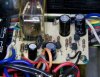
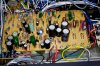
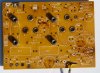
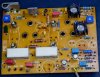
I will now continue them here. Audiokarma users: ecluser and Alienz have been providing me with some great information and help. Alienz has a Luxman SQ-507 and posted a couple of pictures of his output amplifier module. I have a couple pictures of mine. You can see they are similar but different. Because there isn't an accurate schematic of the L-507, I traced out my board and created one. That picture is also posted in the starting thread. One thing that was interesting in determining the real schematic was that the closest Luxman output amplifier schematic to the L-507 is the L80V. The actual component physical location in the L80V is completely different but the circuit is really, really close. I have a couple of pictures of the differences and a cross-reference of the circuit parts (output amplifier only) of the L-507 and L80V.
Sorry for being so long-winded on this posting but I hope other Luxman vintage amplifier owners will find the information useful. I will be adding the rest of the L-507 recap and any new schematic information in this thread.
-Sonavor
At that time I dug out my Luxman L-507 which had been in storage for a while because I wanted to see if it worked. I wasn't really surprised that it didn't. I bought the amplifier second-hand from an authorized stereo store in 1976. A couple of years later it developed a problem in the right channel where the amplifier had to warm up before it would work. The speaker protection relay would click on and off while the warm up process took place. I started just leaving the amplifier on all the time. It never had any problems when I did that. On two occasions I had a (supposedly expert) technician look at it to fix the problem. They never could find the problem. I finally stopped using it around 1988.
In 2010 when I decided to see if I could resurrect this nice vintage amplifier I started looking for a service manual or a schematic. That was when I started the Audiokarma thread. I couldn't find a service manual but I found a couple of schematics. One was for the SQ-507 and one was for the L-507 (my amplifier). I also found the ton of information on this site about refurbishing vintage audio and the necessity to replace the electrolytics. So that was the first step.
As I started on the recap I found that my L-507 didn't really match either the SQ-507 or the L-507 schematics. They were close but not the same. One clear difference was on the output amplifier schematic. The SQ-507 shows eight transisitors. The L-507 schematic shows nine transistors. My L-507 has ten transistors.
There are pictures of the schematics and latest recap on the other thread. http://www.audiokarma.org/forums/showthread.php?p=5402159#post5402159
The recap went smoothly and I was impressed when the amplifier came to life. It still needed a good cleaning of the switches but it was working. I also discovered a problem with the speaker protection relay. Its contacts were really corroded so I replaced it. The old L-507 was pretty much back to the way it was when I put it away....the warm up problem on the right output amplifier module was still there. I had hoped that was a capacitor related problem but it wasn't. I verified it is a heat issue on the suspect output amplifier module by using a heatgun (carefully) to heat up just that board before first turning on the L-507 for the day. When I did that the problem didn't occur. So I did some more trouble-shooting in vain and decided to shelve it until maybe I could find another L-507 to compare to.
A few weeks ago I aquired a second L-507 amplilfier. It was a unit that was advertised as having problems driving speakers. It turned out to be a really nice amplifier. It is in excellent shape....better cosmetically than mine I think. I did a quick test on my variac/dim bulb tester and it passed. When I had power on it I could hear the protection relay click just once as it is supposed to and stayed on. So I swapped the right channel output board of this new L-507 with my old one. Sure enough, the warm up problem in my old amplifier went away. So I was in business.
The recapping of the new L-507 and description of circuit differences start in the other thread - http://www.audiokarma.org/forums/showthread.php?p=5402159#post5402159
I will now continue them here. Audiokarma users: ecluser and Alienz have been providing me with some great information and help. Alienz has a Luxman SQ-507 and posted a couple of pictures of his output amplifier module. I have a couple pictures of mine. You can see they are similar but different. Because there isn't an accurate schematic of the L-507, I traced out my board and created one. That picture is also posted in the starting thread. One thing that was interesting in determining the real schematic was that the closest Luxman output amplifier schematic to the L-507 is the L80V. The actual component physical location in the L80V is completely different but the circuit is really, really close. I have a couple of pictures of the differences and a cross-reference of the circuit parts (output amplifier only) of the L-507 and L80V.
Sorry for being so long-winded on this posting but I hope other Luxman vintage amplifier owners will find the information useful. I will be adding the rest of the L-507 recap and any new schematic information in this thread.
-Sonavor
Last edited: