• The move to the new server is done. There are some software and database maintenance updates in process. This has us passing the hat around to help out. We appreciate any donations. Seriously, even a dollar helps. The payment page may be found here - https://www.audiokarma.org/support.html

Luxman L-85V amp rebuild - replacement parts?

santashooter

Active Member
Hi there- i just got my hands on a luxman L-85V amplifier with blown output boards.
Upon getting it home, i have taken out the amplifier boards, and detached the output transistors.
I would like to totally rebuild the amplifier boards, there have been some warmth generated a couple of places, and one boards has at least two burnt resistors.
The caps are easily sourced, but if someone has a parts list for mouser - especially with input on replacement transistors, it would be greatly appreciated, as i wouldn't know how to find suitable replacement transistors.
I have another project - an SX-727 receiver i am working on, and i am trying to get the parts for both machines on the same order ;)

here are some pictures:


Register to hide this ad
Of course, if someone has suggestions/insight into other issues this amp might have, this would be greaty appreciated as well!
 
Might as well make a list and for anything that Mouser does not have, old, obsolete, just post and some kind soul will drop in and recommend a well drop in replacement.

I haven't seen a lot of these discussed here on AK. I don't know if the Luxman Yahoo group has much info on this unit either but it is well worth the work to bring it back. Love the grab handle design of the heat sink for this unit.

http://audiokarma.org/forums/index.php?threads/looking-for-2sb681-2sd551-or-analog.328266/
Talks about the output transistor replacement recommendation.

Any hot spots, up the resistor if that is what was getting hot and mount it off the board. Insulate the legs if you think it is necessary. Just a cm or so off the board will help a lot with cooling of any hot component.

If those diodes are the V1212 or VD1122 they are replaced with 1n4148s in pairs or singles. There are some techs that don't replace them on site, though. I'm not looking at the parts list, just remembering a few Lux units I've seen.
 
Last edited:
Might as well make a list and for anything that Mouser does not have, old, obsolete, just post and some kind soul will drop in and recommend a well drop in replacement.

I haven't seen a lot of these discussed here on AK. I don't know if the Luxman Yahoo group has much info on this unit either but it is well worth the work to bring it back. Love the grab handle design of the heat sink for this unit.

http://audiokarma.org/forums/index.php?threads/looking-for-2sb681-2sd551-or-analog.328266/
Talks about the output transistor replacement recommendation.

Any hot spots, up the resistor if that is what was getting hot and mount it off the board. Insulate the legs if you think it is necessary. Just a cm or so off the board will help a lot with cooling of any hot component.

If those diodes are the V1212 or VD1122 they are replaced with a pair of 1n4148s in series. I'm not looking at the parts list, just remembering a few Lux units I've seen.

From the schematic it seems the output transistors should be 2SC1079 and 2SA679 - not 2SB681 and 2SD551? - could Luxman had used both in the amplifer, or was mine tampered with?

Also - i do not have VD1122 but i do have VD122K diodes?
 
I google the transistor number and frequently an AK post comes back with a swap recommendation. I don't know the VD122k but someone might.
 
here is a list of the amplifier board - i have found the mouser part number for resistors and capacitors:
I have trouble finding info on diodes and the transistors...
I hope that someone can give me some guidance.

R01 - Resistor: 4.7K - - Mouser: 588-OD472JE
R02 - Resistor: 220 - - Mouser: 588-OD221JE
R03 - Resistor: 220 - - Mouser: 588-OD221JE
R04 - Resistor: 100K - - Mouser: 588-OF104JE
R05 - Resistor: 33K - 0.5W - - Mouser: 588-OF333JE
R06 - Resistor: 33K - 0.5W - - Mouser: 588-OF333JE
R07 - Resistor: 3.3K - - Mouser: 588-OD332JE
R08 - Resistor: 8.2K - 0.5W - - Mouser: 588-OF822JE
R09 - Resistor: 8.2K - - Mouser: 588-OF822JE
R10 - Resistor: 180 - 0.25W - - Mouser: 588-OF181JE
R11 - Resistor: 3.3K - - Mouser: 588-OD332JE
R12 - Resistor: 680 - - Mouser: 588-OD681JE
R13 - Resistor: 5.6K - - Mouser: 588-OF562JE
R14 - Resistor: 100K - - Mouser: 588-OF104JE
R15 - Resistor: 100 - - Mouser: 588-OD101JE
R16 - Resistor: 4.7K - - Mouser: 588-OD472JE
R17 - Resistor: 47K - 0.5W - - Mouser: 588-OF473JE
R18 - Resistor: 150 - - Mouser: 588-OF151JE
R19 - Resistor: 2.4K - - Mouser: 588-OF242JE
R20 - Resistor: 82 - 1/2W - - Mouser: 588-OF820JE
R21 - Resistor: 82 - 1/2W - - Mouser: 588-OF820JE
R22 - Resistor: 0.33 - 5W - - Mouser: 71-CP0005R3300JE66
R23 - Resistor: 0.33 - 5W - - Mouser: 71-CP0005R3300JE66
C01 - Capacitor: 10uF - 16V - - Mouser: 647-USA1C100MDD
C02 - Capacitor: 220pF - - Mouser: 594-D221K20Y5PL63L6R
C03 - Capacitor: 47uF - 10V - - Mouser: 647-UHE2A470MPD
C04 - Capacitor: 0.04uF - - Mouser: 75-565RZ5UBA102EU403
C05 - Capacitor: 33pF - - Mouser: 75-561R10TCCQ33
C06 - Capacitor: 100pF - - Mouser: 594-D101K20Y5PL63L6R

C08 - Capacitor: 47uF - 63V - - Mouser: 647-UHE2A470MPD
C09 - Capacitor: 2.2uF - 100V - - Mouser: 647-UPS2A2R2MDD1TD
C10 - Capacitor: 2.2uF - 100V - - Mouser: 647-UPS2A2R2MDD1TD
C11 - Capacitor: 47uF - 6.3V - - Mouser: 647-UKA0J470MDD1TD
C12 - Capacitor: 33uF - 10V - - Mouser: 647-UVR1A330MDD
C13 - Capacitor: 100pF - - Mouser: 594-D101K20Y5PL63L6R
C14 - Capacitor: 100pF - - Mouser: 594-D101K20Y5PL63L6R
D01 - Diode: VD112K - (2X1N4148 in series) - Mouser: 750-1N4148-G
D02 - Diode: VD112K - (2X1N4148 in series) - Mouser: 750-1N4148-G
D03 - Resistor: 4.7K - - Mouser: 588-OD472JE

Z01 - Zener Diode: 12V? - WZ120 - - Mouser: 863-1N5927BRLG
Q01 - Transistor: 2SA620 - - Mouser: 522-ZTX795A
Q02 - Transistor: 2SA620 - - Mouser: 522-ZTX795A
Q03 - Transistor: 2SC1940 - - Mouser: 512-KSC2690AYS
Q04 - Transistor: 2SC1940 - - Mouser: 512-KSC2690AYS
Q05 - Transistor: 2SC815 - - Mouser:512-KSC815YTA
Q06 - Transistor: 2SC1940 - - Mouser: 512-KSC2690AYS
Q07 - Transistor: 2SC1940 - - Mouser: 512-KSC2690AYS
Q08 - Transistor: 2SC734 - - Mouser:512-KSC1845FTA

Q09 - Transistor: 2SD382 - - Mouser: 863-MJE15030G
Q10 - Transistor: 2SB537 - - Mouser: 863-MJE15031G
Q11 - Transistor: 2SC1079 - - Mouser: 863-MJ21193G
Q12 - Transistor: 2SA679 - - Mouser: 863-MJ21194G

Also - i can't seem to find voltages coming from the power supply, anywhere in the manual? - can someone help here? - i would like to check if the power supply is healthy. :)
 
Last edited:
Looking at the schematic the D01 and D02 diodes are labeled as D501 and D601 along with D502 and D602 since they are on the amp boards the first number was left off. The schematic shows them as VD1221 and a pair of 1N4148 in series is the replacement.

Further, on the schematic the D03 is shown as a resistor. You need to check the board for what is installed.
 
I have rebuilt L309V boards which are very close. They were that bad one even had a hole burnt through....

Get rid of the tantalum caps, they are the best choice IF they are okay, and the worst if not okay. Many times they are not. Especially C512/C612, since they might have suffered reverse voltage at moment of defectiveness.
Concensus seems to be that cap in the feedback loop is important for low distortion, maybe put in a bipolar cap there (of same or somewhat higher capacitance).

You might rethink the bias circuit, as it is made in a stupid way (open circuit potentiometer taper---> higher bias current, who knows it is the bias arrangement killing those old Luxman amps).

Replace all transistors, indeed, it would be a PITA if one "measuring good" would be deteriorated being the cause of a failure.
 
Looking at the schematic the D01 and D02 diodes are labeled as D501 and D601 along with D502 and D602 since they are on the amp boards the first number was left off. The schematic shows them as VD1221 and a pair of 1N4148 in series is the replacement.
Duly noted, thanks!

Further, on the schematic the D03 is shown as a resistor. You need to check the board for what is installed.
D03 is a resistor on the board - it seems to be a 4.7K resistor installed.
 
I have updated the component list above with the items i have so far.
If you have any thoughts on the parts i have found for replacement, input would be greatly appreciated!

Otherwise i will add capacitors for the power supply to the list as well, before placing my order :)

Then hopefully i will have the parts i need :)
 
One well known cap tester, cap knowledgeable AKer, ConradH recommends increasing all under 35V caps to 35V. If you have the room for this (height might be an issue but probably not on the amp boards) you might consider that. Seems there are some 10V and 16V caps in the amp. Checking C11, the price is the same the size is the same, going from 47µF 6.3V to the 47µF 35V cap. Check yourself for all of them, don't trust someone on AK for doing the work for you.

If you are going to be doing this sort of thing, rebuilding, and will run into a few VD double diodes, it is cheap to buy 100 of these for a couple bucks (14DKK) instead of buying a let's say 8 for 5½DKK.
 
One well known cap tester, cap knowledgeable AKer, ConradH recommends increasing all under 35V caps to 35V. If you have the room for this (height might be an issue but probably not on the amp boards) you might consider that. Seems there are some 10V and 16V caps in the amp. Checking C11, the price is the same the size is the same, going from 47µF 6.3V to the 47µF 35V cap. Check yourself for all of them, don't trust someone on AK for doing the work for you.

If you are going to be doing this sort of thing, rebuilding, and will run into a few VD double diodes, it is cheap to buy 100 of these for a couple bucks (14DKK) instead of buying a let's say 8 for 5½DKK.
Thanks for the input on the caps - I will go through the list and check! - i assumed going as close to the service manual as possible was preferable?
I will look into bulk prices on some of these, as you say i have a couple of amps now, and who knows how many are going to come through here - ordering cost 20 euro's unless the order total is above 50, so it is worth bulking things together! - much appreciated!
 
I wish I kept notes from my rebuild. I also had L-85V with burned amp boards and I had to do a full rebuild (all parts). I have since sold it and I think I gave the service manual with my notes to the buyer. All I remember that I was able to source all parts from Mouser.
 
Another thing: can someone tell me, if i can power on the amp without the amplifier boards in it, to test the power supply - and what i should measure for? - It bothers me the schematic doesn't list voltages :(
 
Duly noted, thanks!


D03 is a resistor on the board - it seems to be a 4.7K resistor installed.

I am not an expert but I think the D03 shouldn't be a resistor! In my luxman M1600 (which uses the same board) D03 is a special green component that is placed closely to the heatsink, I think to improve bias temperature stability.

How did the rebuild work out?

WP_20160910_11_43_09_Pro.jpg
 
Hi everybody - I finally got the chance to get back to this amp - my newly restored amplifier board is now working.
The state of the amp is: I have one restored amplifier board, and one original - it is equipped with new Onsemi output transistors in both channels. It starts up on my bulb tester, and the relay clicks in after a few seconds. Now i am measuring and adjusting idle current and DC offset on both channels. The orignal channel is easy with 50mA Idle current and 2.1mV DC offset - but the newly restored channel is bothering me: I have 26mA in the idle current (and can't get it higher with the trimmers) and -221mV on the DC offset, and I can't get i lower. (I know it is a negative value, but turning the potentiometer up, increases my distance to 0 and too high causes the relay to kick in). Do any of you have any ideas? - all components (Except the trimmers) have been changed to new ones of equal value - the only tradeoffs have been either a higher wattage for resistors that was running hot before or a narrower tolerance. - should I try cleaning the trimmers on the board maybe?
 
-221mV on the DC offset, and I can't get i lower. (I know it is a negative value, but turning the potentiometer up, increases my distance to 0 and too high causes the relay to kick in). Do any of you have any ideas?

The polarity of the DC can be changed by reversing the meter leads. Not really significant the sign of the DC offset in most cases. Sorry I can't help on the repair but sure am glad you are moving forward on this one.
 
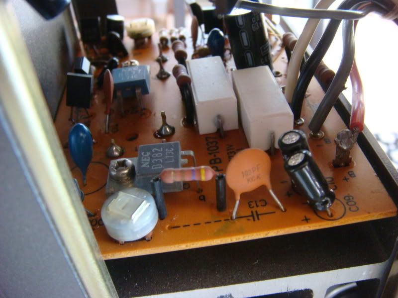
Maybe you can help with a little mystery: One my original board i have a resistor i can't locate in the manual:
Picture of mine here:
IMG_4491.jpg


and this picture I found on the internet:
DSC07541.jpg


Now, from my board - i read 4.7 Ohms, but the one i found on the internet seems to be 470 Ohms - since i can't locate it in the manual, i simply don't know which is right... (the one in my board reads 4.8 ohms when measured)
 
Back
Top Bottom