• The move to the new server is done. There are some software and database maintenance updates in process. This has us passing the hat around to help out. We appreciate any donations. Seriously, even a dollar helps. The payment page may be found here - https://www.audiokarma.org/support.html

Luxman R-1030 recap

Hi,

I am recapping a Luxman R-1030 for a friend and have two small questions.

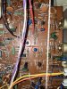
There are elco's in a type of housing I have not seen in my previous recap projects: little blue elco's. Are they also to be replaced? (see picture)

Second question: The schematics I have from this amp (from hifiengine) is too poor in quality so the bottom circuit flow on the circuit board is not readable. At this point I am just taking my time and hunting down to find the right points of elco's to desolder on the bottom, but maybe there is an easier trick to find corresponding soldering points from eclo's on top?

Thanks in advance !
Dieter
 

Attachments

  • IMG_2454.jpg
    IMG_2454.jpg
    196.3 KB · Views: 63
Register to hide this ad
There are elco's in a type of housing I have not seen in my previous recap projects: little blue elco's. Are they also to be replaced? (see picture)

Those are tantalum caps. They are low leakage caps, use UKL (get it before it is unavailable) or film if you decide to replace them.

You could use a small flashlight and shine the spot you are interested and look at from the solder side. Or you could hook your multimeter to one of the legs and hunt down the solder side with the other.
 
usually, i have found that resistor leads are bent inwards and capacitor leads are bent outward. not always but it seems pretty common.
 
higher noise floor. It will sound fine but if you compare it to a properly Low noise, low leakage redone unit you will hear a difference.

MTF did that with a pair of SX-1050s using regular caps in one then did another with UKL where the low noise caps were and posted about a difference.
 
What is the impact of using elco's with same specs, but different series than UKL?
Ditto BlueShadow. Other than the regular specs, the critical spec in here is the leakage current. It doesn't need to be KL from Nichicon, you could also use the TWL series from Rubycon or the MAL2013 series from Vishay.
You could also stay with new tantalum.
Looking at your pictures, most of them have enough space to use film in there.
 
Hi Dieter,

At the moment i'm working on one also.
Had several problems with asymmetrical clipping and tuner function wasn't working at all.

Turned out the flammable resistors were open or had very high resistance.
At some point the amp section had only 8 watts RMS before clipping on the negative sinewave.

IMG-20221226-WA0005.jpg

After I replaced those resistors I got about 30,3 watts RMS. And further up it's clipping nicely on both positive and negative sinewave.

20221226_011315.jpg

On your picture I can see that same resistor looks bad. Some of the 470 ohms resistors measured 50k ohms. Way out of spec.

20221226_011628.jpg

The transistor Q601 was replaced with 2SB647 and the SA798 was replaced with twin KSA992

Hope this will help you with this nice receiver.

Cheers, Roger
 
Just wanted to say thanks for this information.

I recently bought an R-1030 as non-working with no sound from any source other than the odd faint hiss and crackle. Checked the resistors listed in the previous message and found them all to be either failed or miles out of spec. Once replaced decent sound was restored on all sources. DC offset and idle both fine.

I am getting some static bursts so will now investigate the transistors.
 
I've just bought a Luxman R1030 receiver. It sounds wonderful! It works great most of the time but once in a while some crack comes from the speakers. I had a Pioneer SX 525 which I fully recovered doing a almost full recap and transistors replacement, thanks to the many information available here. Unfortunately I can't find much about the luxman r1030. Could any of you help me identify or tell me which capacitors are in the signal path? I will try to follow the same pattern of the 525, using nichicon UKL, FW and wima MKS.
 
Get the service manual. Clean everything and flush all the pots and switches. Then reassess things. This era of audio gear the in signal caps tend to be films which probably don’t need to be changed or they are “orange” and electrolytic which can be beneficial to replace.

Overall, get your power related boards and amp drivers attended to first and then your tone and preamp. I always do the tuner last. Even if you don’t listen to the tuner, do it as it will be energized. Also don’t ignore the main power filters.
 
Thank you very much!
I already ordered the 2x 4700uf Mundorf AG mlytic filter capacitors, the same series I used in the Pioneer SX 525 recap, with great results. I will replace the small electrolytics(orange ones incld.) and tantalum for film Wima MKS. For the others I will use nichicon UPW. I hope I'm not missing any capacitor that I should replace with a more audio grade(low ESR) one like UKL. unfortunately I'm still a rookie, very happy to restore successfully the "easy to repair" Pioneer SX 525 :)
This Luxman seems to have a bit more sophisticated kind of sound signature and I would like to pull the best I can from it. None of the pots or buttons are noisy. Only some loud crack noises appear after some 1-2 hours. It lasts 4-5 seconds and then after a hour or two it make the same noise again. If I quickly turn the volume down the noise goes down too. I'm avoiding turning it on again before replacements...
 
Resoldering all the boards and pay attention to all the transistors. Sounds like a crack that is expanding with heating. As for your power filters, I would have gone up to 6800uf. Put a good quality 2.2uf poly cap as a bypass on your mundorfs and you should be fine. 1kv. Replace your insignal electrolytic’s with šame value nichicon mues bipolar and then on the foil side tack a .01 uf wima. I have found that approach to sound better vs just using a wima film.
 
Thank you
I was afraid to put such a higher value on power filters, as I taught that it could stress other components and I would not be able to figure out what to do then. I opted for the 4700uf 40v Mundorf instead of the original 4700uf 35v.

When you're saying that I should put a 2.2uf poly cap as a bypass are you referring to the 4700 capacitors?

As for the same values, should I care about voltage? I usually increase the voltages a bit when I replace capacitors...

Unfortunately I couldn't find any information about witch capacitors are in the signal path on this receiver. I can't read that in the schematic so I can't figure it out by myself. I'm assuming that the small tantalum are in the signal path and the orange capacitors.

"Replace your insignal electrolytic’s with šame value nichicon mues bipolar and then on the foil side tack a .01 uf wima".
Can you tell me where or specify which ones are these?

I have to wait for some parts to arrive( including a better solder wire) and in about a week I hope to start the recaping.
 
Thank you
I was afraid to put such a higher value on power filters, as I taught that it could stress other components and I would not be able to figure out what to do then. I opted for the 4700uf 40v Mundorf instead of the original 4700uf 35v.

When you're saying that I should put a 2.2uf poly cap as a bypass are you referring to the 4700 capacitors?

As for the same values, should I care about voltage? I usually increase the voltages a bit when I replace capacitors...

Unfortunately I couldn't find any information about witch capacitors are in the signal path on this receiver. I can't read that in the schematic so I can't figure it out by myself. I'm assuming that the small tantalum are in the signal path and the orange capacitors.

"Replace your insignal electrolytic’s with šame value nichicon mues bipolar and then on the foil side tack a .01 uf wima".
Can you tell me where or specify which ones are these?

I have to wait for some parts to arrive( including a better solder wire) and in about a week I hope to start the recaping.
This is filtering. The engineers would have gone higher but the finance guys didn’t want to spend the $1.25. Adding the films to these will block all the DC. Don’t be afraid of increasing the uf a bit. As for voltage, the higher voltage has better specs. You are still in the afraid stage. That will pass
 
This is filtering. The engineers would have gone higher but the finance guys didn’t want to spend the $1.25. Adding the films to these will block all the DC. Don’t be afraid of increasing the uf a bit. As for voltage, the higher voltage has better specs. You are still in the afraid stage. That will pass
Thank you very much! After I put the the Mundorf caps I've noticed that the sound, although more clean, it became a bit too bright. Then I bypassed them with temporarily with wima 0,47uf 50v film cap, just to try, because I'm still waiting for more capacitors to arrive, and the sound became much rounder. I'm guessing that with the 2.2uf will probably will be even better...
 
Thank you very much! After I put the the Mundorf caps I've noticed that the sound, although more clean, it became a bit too bright. Then I bypassed them with temporarily with wima 0,47uf 50v film cap, just to try, because I'm still waiting for more capacitors to arrive, and the sound became much rounder. I'm guessing that with the 2.2uf will probably will be even better...
If you are going to bypass, go withhold the Mundorf .01uf evdo oils
 
Back
Top Bottom