• The move to the new server is done. There are some software and database maintenance updates in process. This has us passing the hat around to help out. We appreciate any donations. Seriously, even a dollar helps. The payment page may be found here - https://www.audiokarma.org/support.html

Luxman R-117 Turn On Thump, trying to figure out problem

33713

Active Member
SO, I picked up a R-117 a while back, fixed a couple age related problems, and got stuck here, so have not been using.

I already fixed the remote issue that may of these have, by stumbling into a small dead, 20uf cap on the power relay board.
I already recapped the whole power supply section in hopes that I found a problem there, but did not.

Here is the symptom: Turn on, instant loud turn on transient. Instant, no relay delay at all. If I turn it on without the speakers "on" it does not happen, and I can engage the speakers with the speaker button with no issue at all. on and off all day long, quiet. I mention this because many people have speaker relay issues and replace them. I do not think that will fix mine.

I am trying to figure out what part controls the power and or speaker relays. Since I have recapped the power supply, and back up power supply boards, I am now wondering if it is on the main amp board or something. I think I am looking for a Capacitor that went bad, maybe in combination with an IC that looks for DC/shorts etc. But the capacitor would cause the relay delay while filling up.

Here is the full service manual:

Any help would be greatly appreciated! Thanks -Marc
 
Register to hide this ad
since you have the service manual, did you set the bias and DC offset? if not, might be a first step.

typically a turn on transit indicates a bit of dc on the protection relay.
 
since you have the service manual, did you set the bias and DC offset? if not, might be a first step.

typically a turn on transit indicates a bit of dc on the protection relay.
Hello, I forgot to mention that. I did. I just double checked it this morning when I retested this issue and wanted to reopen the case. DC is super low, and on this receiver, it is autobiasing I believe. But DC and or bias were adjusted after I did the power supply a few months ago. TY
 
If I run 2 pair of speakers on mine it's starts to not be happy with the volume at 11:00 , power on or off I get a loud thump through the speaker from one channel. I can turn off both pairs of speakers and the volume all the way off and it will still do a loud thump at power on or off, the red indicator on the volume isn't even on yet.

I bought it cheap from a guy that said the speaker relays were replaced , they were but it had a dead channel so I took it to my tech , they found the relays had indeed been replaced with the wrong ones. They were unable to source ones with all the correct ratings but found suitable ones.

Worked great for a couple months then the above issue started , took it back to them and they really didn't find anything so now I just run one set of speakers and it has no issue ?
I believe this is a finicky model , people seem to have weird issues with them, though your not having a relay issue I wouldn't over look the speaker relays as they seem to be a common problem area creating various issues. If you get a thump before the relay engages how is power getting to a speaker , is there a path around the speaker relays or are they being engaged at power up by something , maybe pull your jumpers and see if it still happens.
 
I think I am looking for a Capacitor that went bad, maybe in combination with an IC that looks for DC/shorts etc. But the capacitor would cause the relay delay while filling up.
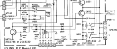
That's what I think as well. C654, 47µF, 50V I reckon. (see pp21, and 'Speaker Terminal P.C. Board')
 
Also take a look at C655 47uf/16V

Protection circuit is somewhat unusual, CPU controlled TA7317P based. Relays for both protection and speaker selection. Key point being it's a parallel connection to both protect circuit and speaker selection so a fault in the speaker select will cause a "pop". Both TA7317P and speaker select use C655 for mute timing.

Test ZD651(short?), Q653,2,1.
Also measure Vdc during power up at MP653
Pin 6... spkr select power

Wanting pin 6 to be low during mute period
 

Attachments

  • R117.png
    R117.png
    162.9 KB · Views: 9
SO, I picked up a R-117 a while back, fixed a couple age related problems, and got stuck here, so have not been using.

I already fixed the remote issue that may of these have, by stumbling into a small dead, 20uf cap on the power relay board.
I already recapped the whole power supply section in hopes that I found a problem there, but did not.

Here is the symptom: Turn on, instant loud turn on transient. Instant, no relay delay at all. If I turn it on without the speakers "on" it does not happen, and I can engage the speakers with the speaker button with no issue at all. on and off all day long, quiet. I mention this because many people have speaker relay issues and replace them. I do not think that will fix mine.

I am trying to figure out what part controls the power and or speaker relays. Since I have recapped the power supply, and back up power supply boards, I am now wondering if it is on the main amp board or something. I think I am looking for a Capacitor that went bad, maybe in combination with an IC that looks for DC/shorts etc. But the capacitor would cause the relay delay while filling up.

Here is the full service manual:

Any help would be greatly appreciated! Thanks -Marc

May I ask what the issue with your remote was? I've had an issue with both my 117's where if using the remote to turn the volume down it shuts the 117 off...but this is with the same remote. Never on volume up...always down.

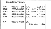
I'm not seeing any 20uf caps anywhere on the schematics...or are you talking about the one electrolytic cap inside the remote? Cap number on the schematics if not if you can remember please?
 
Also take a look at C655 47uf/16V

Protection circuit is somewhat unusual, CPU controlled TA7317P based. Relays for both protection and speaker selection. Key point being it's a parallel connection to both protect circuit and speaker selection so a fault in the speaker select will cause a "pop". Both TA7317P and speaker select use C655 for mute timing.

Test ZD651(short?), Q653,2,1.
Also measure Vdc during power up at MP653
Pin 6... spkr select power

Wanting pin 6 to be low during mute period
Awesome, I will check this out asap! TY
 
May I ask what the issue with your remote was? I've had an issue with both my 117's where if using the remote to turn the volume down it shuts the 117 off...but this is with the same remote. Never on volume up...always down.

I'm not seeing any 20uf caps anywhere on the schematics...or are you talking about the one electrolytic cap inside the remote? Cap number on the schematics if not if you can remember please?
Hello there. It was on the backup power supply board under the speaker terminals. I just got lucky I think and tested them in circuit. I thought it was a 20uf, but maybe it was the 100uf. I ended up replacing all electrolytic on there.
 

Attachments

  • Screenshot 2026-09-06 at 11-57-59 Luxman R 117 Service Manual - Luxman-R-117-Service-Manual.pdf.png
    Screenshot 2026-09-06 at 11-57-59 Luxman R 117 Service Manual - Luxman-R-117-Service-Manual.pdf.png
    44.9 KB · Views: 1
Hello there. It was on the backup power supply board under the speaker terminals. I just got lucky I think and tested them in circuit. I thought it was a 20uf, but maybe it was the 100uf. I ended up replacing all electrolytic on there.

Ok thanks. What was the issue with your remote?

EDIT: So C705?

IMG_20190711_143921643.jpg
 
Last edited:
Also take a look at C655 47uf/16V

Protection circuit is somewhat unusual, CPU controlled TA7317P based. Relays for both protection and speaker selection. Key point being it's a parallel connection to both protect circuit and speaker selection so a fault in the speaker select will cause a "pop". Both TA7317P and speaker select use C655 for mute timing.

Test ZD651(short?), Q653,2,1.
Also measure Vdc during power up at MP653
Pin 6... spkr select power

Wanting pin 6 to be low during mute period
ZD651 is good. no short, open one way, .727 the normal way
C655 I had already replaced with nichicon PW, measuring 46uf in circuit right now
Q651in circuit .657 .662
Q652 on circuit .651 .656 measured backwards, I get like cap reading on center pin
Q653 in circuit. A little confused on this one.

BL P1(E)>P2(B) 1.9+++ this rises like a cap charging?
BL P1(E)>P3 (C) .680
BL P3(B)>P2(C) OL
BL P3(B)>P1(E) 1.617


Can you elaborate on the test at power on? I see pin 6 goes to the diode ZD651. Measure before it or after it?
Is it possible this IC is bad if nothing else here seems suspect?

I should mention this too. If I power it down, and then turn it right back on, the pop is not nearly as bad or absent. Give it some time, and it comes back.

Thanks! I really hope I can figure this out, as I do not dare to use it this way. The pop is loud!
 
Ok thanks. What was the issue with your remote?

EDIT: So C705?

View attachment 3831416
I think that would be 705 that was measuring open for me. I actually noted in in another thread about this to help anyone else in the future. Let me look. I was thrilled when it resolved. I had the normal issue. you hit any button and it receives the command, the machine locked up, and kinda shutdown, then came back to life.
 
I think that would be 705 that was measuring open for me. I actually noted in in another thread about this to help anyone else in the future. Let me look. I was thrilled when it resolved. I had the normal issue. you hit any button and it receives the command, the machine locked up, and kinda shutdown, then came back to life.

I see. No I will start to turn it down after a song and a loud snap and it shuts down. I did clean up the remote which was pretty bad but it still does it occasionally.

Before pics of the remote...

RR-117 Remote5.jpg
RR-117 Remote3.jpg

Sorry, I didn't mean to derail your post but the "fixed my remote problem" I've been after for quite awhile now.
 
I see. No I will start to turn it down after a song and a loud snap and it shuts down. I did clean up the remote which was pretty bad but it still does it occasionally.

Before pics of the remote...

View attachment 3831465
View attachment 3831466

Sorry, I didn't mean to derail your post but the "fixed my remote problem" I've been after for quite awhile now.
No problem, hopefully. Just to add a little more info, I am using an old harmony remote. So this shutdown happens regardless of the condition of the remote.
 
No problem, hopefully. Just to add a little more info, I am using an old harmony remote. So this shutdown happens regardless of the condition of the remote.
I did see that in your other post a bit ago. I just thought mine having crud between the contacts was giving it mixed signals causing a shutdown...but nope still did it after cleaning. I'm also thinking of replacing the one cap in the remote...a 47uf 6.3v electrolytic...not sure what it does though.

Another note on your other post if you havent found out yet...the LED on the volume knob stays on the whole time the 117 is powered up independent of the remote.

Wish I could help you but this is beyond my knowledge. All I know from owning one since 1989 is at power up it will dim the house lights a bit. They do thump a bit at power down but not much. I'm using my 117 as a preamp currently that splits a Y cable to a Crown amp and one side to my sub. On this setup it will thump pretty loud unless I follow this shutdown routine. First volume all the way down...sub off...amp off...then finally the 117.

Good luck...it is a great receiver.
 
Can you elaborate on the test at power on? I see pin 6 goes to the diode ZD651. Measure before it or after it?
With unit powered off, red probe to Pin 6 should read close enough to 0Vdc. Then power on and note how quickly (immediately??) the pin 6 voltage comes up.

Pin 6 is fed from unregulated supply then IC651(protect IC) pin 9 then ZD651.
Initially I thought IC mute timing (C655) would also delay how quicly that pin 6 comes up, but I think that's wrong. ZD651 will provide a very slight delay for the pin 6 voltage, ie, need at least 14.7V before diode conducts.
Would need at least 2 seconds between power up and pin 6 stable voltage.

The test is to see if the diode is failing under load, if so then power is sent to spkr selectors and returned on MP653 Pin 1(Set A) and 2(B) to operate Q651, Q652 before amp has stabilized.
 
OK I can check that out tomorrow. I also wanted to show you this. This is Q653. any thoughts? I may beed to remove it to further investigate its status?
 

Attachments

  • Q653.jpg
    Q653.jpg
    114.7 KB · Views: 5
This is Q653. any thoughts?
Doesn't show any error.
Q653 appears to be part of the thermal protection, it will trigger release of speaker select relays.
Since it's a disable function it does not fit your fault situation where the speakers are enabled too quickly before the amp has normalized
 
Doesn't show any error.
Q653 appears to be part of the thermal protection, it will trigger release of speaker select relays.
Since it's a disable function it does not fit your fault situation where the speakers are enabled too quickly before the amp has normalized
OK, was able to set up and test pin 6 this am. Also, it's very clear with the speaker relay board in your hand that the relay is engaging immediately at turn on and releasing at turn off. The test shows this. Black at chassis ground, red at pin 6, that the voltage is about 9.15 and never goes up? I can post a video or two somewhere if you would like to see the behavior. Please let me know if you can think of another test to run. Thanks!
 
With the unit powered off I assume Pin 6 was 0Vdc, C758 is only 1uf so nothing to discharge (D760 orientation appears incorrect). Also assume Pin 6 immediately jumps to 9.15Vdc, ie wanted delay of 2seconds not observed.

Plz confirm immediate jump from 0V to 9.15Vdc, no 1-2second delay

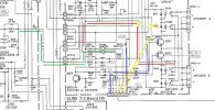
I'm stumped, the amp appears to work as designed, had a look for service bulletins... Appears that a delay at power on needs to be added for the speaker select relays, possibly adding a cap on pin 6 (with a bleed resistor??), possibly better would be to cut traces (see yellow below) and take audio feed from pins 3&5, this is above my pay grade maybe one of the techs can propose a solution.

Fig below tries to illustrate problem.
Green line, Usual audio out from power amp through protect relay RY655
Red line passes audio to speaker select relay
Blue line is power for speaker select relays, through zener to spkr switches then onto Q651,2, appears to be no delay
Yellow line, possible solution??? take audio from after the speaker protect relay which includes a power on delay C655
 

Attachments

  • R117_spkrs.jpg
    R117_spkrs.jpg
    116.6 KB · Views: 3
Back
Top Bottom