• Please note that Audiokarma will be offline briefly for updates early on Monday morning, September 28th.

Luxman R-3045 (and other models) Replacement Diodes

Daryl S

New Member
I have been searching for a replacement diode for an R-3045 receiver I salvaged from a 2nd hand store and want to restore. There are numerous diodes numbered US1070 in the service manual but I can find no information on that particular diode anywhere. I see it is used in other Luxman amp (L-480 and L-580) and receiver models (R-3055 and R-2050) and goes by Luxman part number TD0197. On the R-3045 it's used in diode locations D307, D308, D309, D310, D312, and D313 on the PB-1314 audio board to name a few.

If anyone has a data sheet for that diode or, better yet, a suitable replacement, it would be very appreciated.

Thanks!
 
Register to hide this ad
Welcome to AK..
@century tek makes sense... Luxman rescued will required more than diode questions. Luxman is a fine brand so pics and observations are welcome.
 
I am just digging into this unit and doing a bit of research into how difficult it may be to find any replacement components and that was a diode number I'd never seen before. I do not know for a fact if any of the US1070 diodes are bad yet but will be testing some on a multimeter this evening, if the diagnosis leads in that direction.

By way of a bit more background, when I opened this unit last night, I saw the main 3 amp fuse was blown. When I put a new one in and powered it up with the dim bulb tester, the bulb was shining brightly so I fear there is a fault in the power circuit somewhere. I didn't see any obviously burnt components but that's as far as I've gotten to this point other than to acquire and start studying the schematics in the service manual and to open up the unit so that I can reach all the board components. This is only my 3rd SS amp or receiver rescue (Marantz 1070 and Sansui AU-517 were the first two) so I'm relatively new to this and fairly slow yet. This is the first Luxman I've seen in this part of the country so I'd like to get it working. I am hoping I can start working my way through the power circuit diagnosis tonight.
 
It all starts in the power supply section... rectifier diodes down stream to outputs. Pre driver transistors diode checks.. solder joints burnt board signs...
Post pics of board(s) caps etc.. we have members who have eyes like an eagle.. Do it right.. again all starts in the power supply. Do it right and cold test components. luxman's ain't getting any younger and this is no quick fix.
bink.
btw I'd love to get my hands on any luxman... rare as hens teeth in my locale.
 
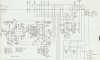
Here is an update on this R-3045 receiver. Last night I tested the PB-1314 board transistors and found these were all shorted: main output transistors Q001A, Q001B, Q002A, Q002B plus Q309A, Q309B, Q308A, Q308B, Q304A, and Q304B. Main outputs Q001A and B are C2579, Q002A and B are A1104. Q304 A and B are 2SC1904BV, Q308 A and B are 2SC1815, and Q309A and B are 2SA1015. These are marked on the attached schematic.

I ran out of time before I had to get the kids to bed so I haven't tested any other components in this circuit but will try to do so in the next couple of days. In the mean time, I am wondering if anyone sees an issue with using these transistors as replacement components:

2SC4467 for the C2579s at Q001A/B, 2SA1694 for the A1104s at Q002A/B, KSC3503 for the 2SC1904BV at Q304A/B, KSC1815 for the 2SC1815 at Q308A/B, and KSA1015 for the 2SC1015 at Q309A/B?

Also, if anyone has advice on other components in this circuit that I should expect to be bad based on the above failures, let me know.

Thank you for your insight and experience!R3045 PB1314 Output and Protection Schematic_failed transistors.jpg
 
It all starts in the power supply section... rectifier diodes down stream to outputs. Pre driver transistors diode checks.. solder joints burnt board signs...
Post pics of board(s) caps etc.. we have members who have eyes like an eagle.. Do it right.. again all starts in the power supply. Do it right and cold test components. luxman's ain't getting any younger and this is no quick fix.
bink.
btw I'd love to get my hands on any luxman... rare as hens teeth in my locale.
I will be cold checking all the components and take my time as I go. Just had time to check transistors last night but I'm expecting some other bad parts based on the number of bad transistors I found. There wasn't any obviously burnt components or burnt spots on the board though. I'll also get some pictures taken and posted.

Thanks for the reply Bink!
 
Hmm, second thread I've looked at today where I can't think of a remotely plausible root cause for the constellation of failed parts. I must be slipping! (Or more likely, self-overrated to begin with...)

One thing occurs to me that might need a double-check: The Q308 and 309 transistors might look like their base-emitter junctions are shorted if they were tested in-circuit, because of the relatively small resistance that's connected across those junctions. Disregard this if those transistors were checked out-of-circuit, or if they exhibited a short other than base-emitter,

I'm particularly puzzled and worried about the Q304 failures. Puzzled because their function is not one where a random failure is likely - much less failing in both channels at the same time!! Worried because, depending on what junction(s) were shorted, harmful levels of current may have flowed in both the bias regulation circuitry and the driver transistors.

It would probably be a good idea to replace those variable resistors that are sort of in the middle of the power amp circuit, even if they test OK - they are the adjustments for setting bias current.

At some point when the rest of the failed/suspect components have been replaced, it would be a good idea to power up the receiver through the DBT without the output transistors (Q001 and 002) installed. Also with no speakers connected. The amp should come into DC balance in that condition, so the protection relay should engage, and it would be safe to do a sound check with headphones at low volume levels. If all appears hunky-dory in those circumstances, then it would be pretty safe to install the output transistors and re-test.

Really can't imagine what happened to the poor thing. Could it have been oscillating? (I'm deeply suspicious of Luxman's idea of putting tone controls in the power amps' feedback loops.) But even then, both channels at the same time??

Bemusedly,

chazix
 
Back
Top Bottom